0-1 DB, 0-10 DB, 0-100 DB
These three dials are the controls for the three-section attenuator,
which is inserted in the output path between the output meter and
the line -matching transformer.
The attenuation in db inserted in
the circuit is equal to the sum of the three control knob settings,
and the reading of the output meter minus the inserted attenuation
is the level of the signal at the generator OUTPUT binding posts.
The attenuator provides a means for reducing the output voltage,
in
.
1 db steps,
to a maximum of 111 db below the level indicated
by the meter.
POWER CABLE
The three-conductor power cable is terminated in a polarized
three-
prong male connector recommended by the National Electrical
Manufacturers1 Association. The third contact is an offset round
pin, added to
a
standard two-blade a-c plug, which grounds the in-
strument chassis when used with the appropriate receptacle. To use
this NEMA plug in a standard two-contact outlet, it is recommended
that instead of breaking off the ground terminal, a 2-prong to 3-prong
adapter be used. The ground connection emerges from the adapter
as a short lead which should be connected to ground for the protec-
tion of operating personnel.
2-3 OPERATION
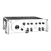
The procedure for operating the Model 206A Low Distortion Audio
Signal Generator is as follows.
1. General
With the instrument plugged into a power source of specified
voltage and frequency, and the power
switch at ON allow a
warm-up period of
a
few minutes. Specified accuracy of
+2%
will be obtained after a few minutes warmup. For maximum
accuracy, however, allow
a
20-30 minute warmup.
NOTE
If
a 230-volt power source is used, check (1)
that power transformer Tl is strappedfor
230-
volt operation (strapping options are shown on
the schematic diagram), and
(2)
that fuse
F 1
is an. 8-ampere Slo-Blo fuse.