Model 214B
General
Information
Table
1-2.
Specifications
OUTPUT
CHARACTERISTICS
Pulse
Amplitude
0.3V
to
looV
into 50 ohm. 5 ranges with cal ibrated vernier
providing continuous adjustment within ranges.
Vernier Accuracy:
± 1
0%
of
setting.
Source
Impedance
Fixed 50 ohm nominal on ranges up
to
10V
. Selectable
50
ohm
nominal
or
high impedance on 10-
JOV
and
JO
-
looV
ranges.
(Note
: with 50 ohm source and load impedance, 10-
JOV
and
JO-
looV
ranges reduce to 5 -
15V
and
15
- 50V respectively).
Polarity:
Positive or negative , switch selectable.
Preshoot,
Overshoot
and
Ringing
: .;; ± 5
0/0
of
pul
se
amplitude.
Pulse
Top
Perturbations
:
.;;
± 5%
of
pulse amplitude.
Transition
Times:
.;; ISns for
le
ading and trailing edge s.
TIMING
Repetition
Rate
10 Hz
to
10
MH
z
in
6 decade ranges. In
30V
-
IOOV
amplitude
range, maxi
mum
repetition rate
is
4
MH
z. Cali
brat
ed vernier
provides
co
ntinuous adjustme
nt
within ranges.
Vernier Accuracy:
±
(1
0%
of setting + 1%
of
full sc
al
e).
Period
Jitler
:
.;;
0.1% + Joops.
Pulse
Position
Pulse Delay
Pulse can be delayed with respect to the Trigger
Output
from
+
IOns
1 +
fi
xed delay I to + I
Om
s. 1 Fixe d delay is 50 ns ±
IOns
J.
Pulse Ad vance
Pulse can
be
delayed with respect
to
the Trigger
Output
from
+
IOns
1- fixed delay I to +
IOm
s. 1 Fixed delay
is
50 ns ±
IOn
s 1.
Controls
5 decade ranges with calibr.ted vernier providing continuous adjust-
men"!
within range
s.
Vernier Accuracy: ±
(1
0%
of
setting + I %
of
full
sc
ale) +
fi
xed delay .
Maximum Pulse Position Duty Cycle: ;;. 50%.
Position
Jitler:
.;; 0.1 % + 50Ops.
Pulse
Width
2
5ns
to
IOms
in
6 decade ranges. Calibrat
ed
vernier provides
continuous
adjus
tment
within range
s.
Vernier Accuracy: ±
(10
% of setting + 1% o
ffull
sc
ale
+ 5ns
).
Width
Jitter:
.;; 0.1 % + 500ps.
Maximum
Duty
Cycle
;;.
10% for
JO
- looV amplitude range .
;;.
50% for
all
other ranges. (max.
10
ms width)
Constant
Duty
Cycle
Mode
(Disabled in External Trigger Mode)
Duty cycle
of
output pulse (hence
output
power) remains constant
when the pulse period
is
changed.
In
this mode the duty cycle limits are:
Typically 8% fixed for
10M
- I
MHz
frequency
ra
ng
e (max.
fr
equency
EXTERNALLY
CONTROLLED
OPERATION
External
Trigger
Mode
. An ou
tput
pul
se
is generated for each
input pul
se.
Gate
Mode
Ga
ting
si
gnal turns on repetition rate generato
r.
First pulse occu rs
af
ter
start
of
gate s
ign
al. and
la
st pulse is always completed even if gate ends
during generation of
la
st pulse.
Bur
st
Mode
(Optional)
Preselected number
of
pulses generated on receipt of tflgger s
ign
a
l.
Number
of
Pul
ses
: I to 9999.
Minimum Spacing between Bursts:
cOOns
.
External
Input
Repetition Rate .
DC
to
10
MH
z.
Sensivitiy:
SOOmV
peak to peak. de coupled.
Slope: Positive or negative.
Trigger Level : Continuously adjustable from 5V to +5V.
Maximum Input Level:
±
looV
.
Trigger Pulse Width :
;;.
IOn
s.
Input
Impedance: 10k ohm nominal.
Manual
Pus
hbutt
on can be used for :
.- triggering single pulses (E
XT
TRIGGER
Mod
e)
- generating gate signals (GA TE Mode)
- triggering pul
se
bursts (BURST Mode)
GENERAL
Environmental
: Instrument operates within
OO
C
to
55
0
('.
Power
Requirements
looV
, 1
20
V, nov or 240V, +5%, - 10
%.
48
Hz to 66 H
z.
360VA max .
Weight
. Net
13
.6
kg
(30
.1 Ib), shipping 15.6 kg (34.3 Ib).
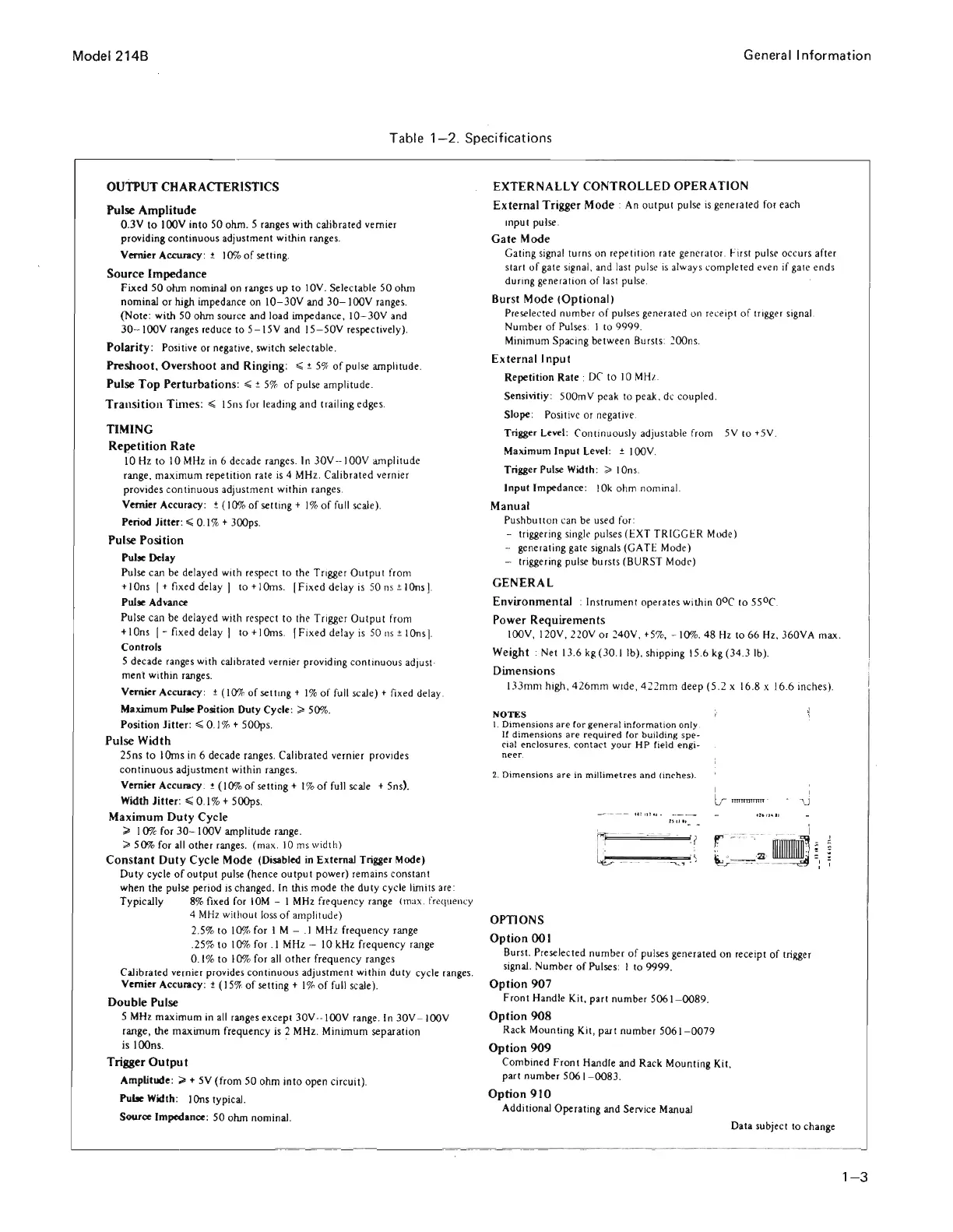
Dimensions
133
mm
high , 4 26
mm
wide, 4 22mm deep (5 .2 x 16.8 x 16.6
in
ches).
NOTES
1.
Dimension
s a
re
t
or
gener
al
informati
on o
nly
.
If
dimensi
ons
are
requir
ed
tor
building
sp
e-
cial
e ncl
os
ur
es,
co
n
tact
yo
ur
HP
fi
e
ld
engi
-
n
eer
.
2. D
im
e n
sions
are
in
millim
e
tre
s
an
d (
inches)
.
r
F
,
=============1
' r
Lb
__
h_
-
~
"J
: )
I
lr
mnmmw
-
,
-
"\j
4
MH
z without loss of amp
li
tude)
OPTIONS
2.5%
to
10% for I M - .1 MHz frequency range
.25%
to
10% for . I MHz - 10 kHz frequency range
0.1%
to
1
0%
for
all
o
ther
frequency ranges
Calibrated vernier provides continuous adjustment within duty cycle range
s.
Vernier Accuracy: ± (15%
of
setting + 1% of full
sc
ale).
Double
Pulse
5
MHz
maximum
in
all
ranges except
JOV
-
looV
range. In 30V- looV
range, the
maximum
frequency
is
2
MH
z. Minimum separation
is lOOns.
Trigger
Output
Amplitude:
;;.
+ 5V (from 50 ohm
into
open c
ir
cuit).
Pube Width: IOns typical.
Source Impedance:
50
ohm nominal.
. -
--
---
-.-
.
---
. -
Option
001
Burst. Preselected number of pulses generated on
re
ceipt
of
trigger
signal. Number of Pulses: I to 9999.
Option
907
Fro
nt
Handle Kit, part number 5061 -
0089
.
Option
908
Rack Mounting Kit, part number 5061 -
0079
Option
909
Combined
Front
Handle and Rack Mounting Kit,
part number 5061 - 0083.
Option
910
Additional Operating and Service Manual
Data subject to change
1- 3
Scans by Artekmedia => 2009