Appendix
A3-1
BURST
PERFORMANCE
TEST
SPECIFICATION:
Preselected number
of
pulses
is
generated on receipt
of
trigger signal.
Number
of
pulses: 1
to
9999.
EQUIPMENT:
Minimum
spacing between bursts: 20005.
Counter/
Timer
50Sl Feedthrough
CAUTION
:
Do
not
overload Feedthrough.
?
14
6
=
c:==J
r=.=J
c::::=::J
~
COUNTER
.
TIMER
0
11
11
0
0 0
0
/0
1\
00
\0
o
~
$?
/
o
50~!
FEEDTHR
OUGH
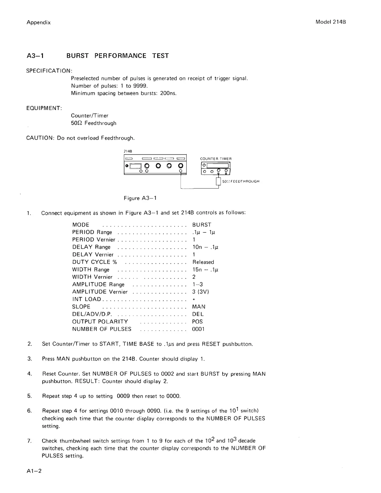
Figure
A3-1
1.
Connect
equipment
as
shown in Figure
A3-1
and
set
214B
controls
as
follows:
MODE BURST
PE
R
100
Range .
..
.
...
.
...
.
.......
.
1M
-
1M
PERIOD Vernier
..
.
..........
.....
, 1
DELAY
Range .
...
.
........
.
.....
10n - .
1M
DELAY
Vernier.
. . . . . . . . . . . . . . . .
..
1
DUTY
CYCLE
%
...
..
.
...
..
...
.
..
Released
WIDTH
Range .
..
.......
. .
...
...
. 15n -
.1M
WIDTH
Vernier . . .
...
..
.........
. 2
AMPLITUDE
Range
...
.
...........
1- 3
AMPLITUDE
Vernier
.. ..
.
..
.
.....
..
3 (3V)
INT
LOAD
.
..
........
..
...
..
. .
..
.
SLOPE . .
..
.....
...........
...
MAN
DELiADV
/D.P.
........
...
. .
....
. .
DEL
OUTPUT
POLARITY
NUMBER
OF PULSES
POS
0001
2. Set Counter/
Timer
to
START,
TIME
BASE
to
.1Ms
and
press
RESET
pushbutton
.
3.
Press
MAN
pushbutton
on the 214B. Counter should display 1.
4. Reset Counter. Set
NUMBER
OF PULSES
to
0002
and start BURST
by
pressing
MAN
pushbutton.
RESULT:
Counter should display
2.
5.
Repeat step 4
up
to
setting
0009
then reset
to
0000
.
6.
Repeat step 4
for
settings
0010
through
0090
. (i.e. the 9 settings
of
the
10
1
switch)
checking
each
time
that
the counter display corresponds
to
the
NUMBER
OF PULSES
setting.
7. Check thumbwheel switch settings
from
1
to
9
for
each
of
the 10
2
and 10
3
decade
switches, checking
each
time
that
the counter display corresponds
to
the
NUMBER
OF
PULSES setting.
Al-2
Model 214B
Scans by ArtekMedia => 2009