Operation
Model
214B
0
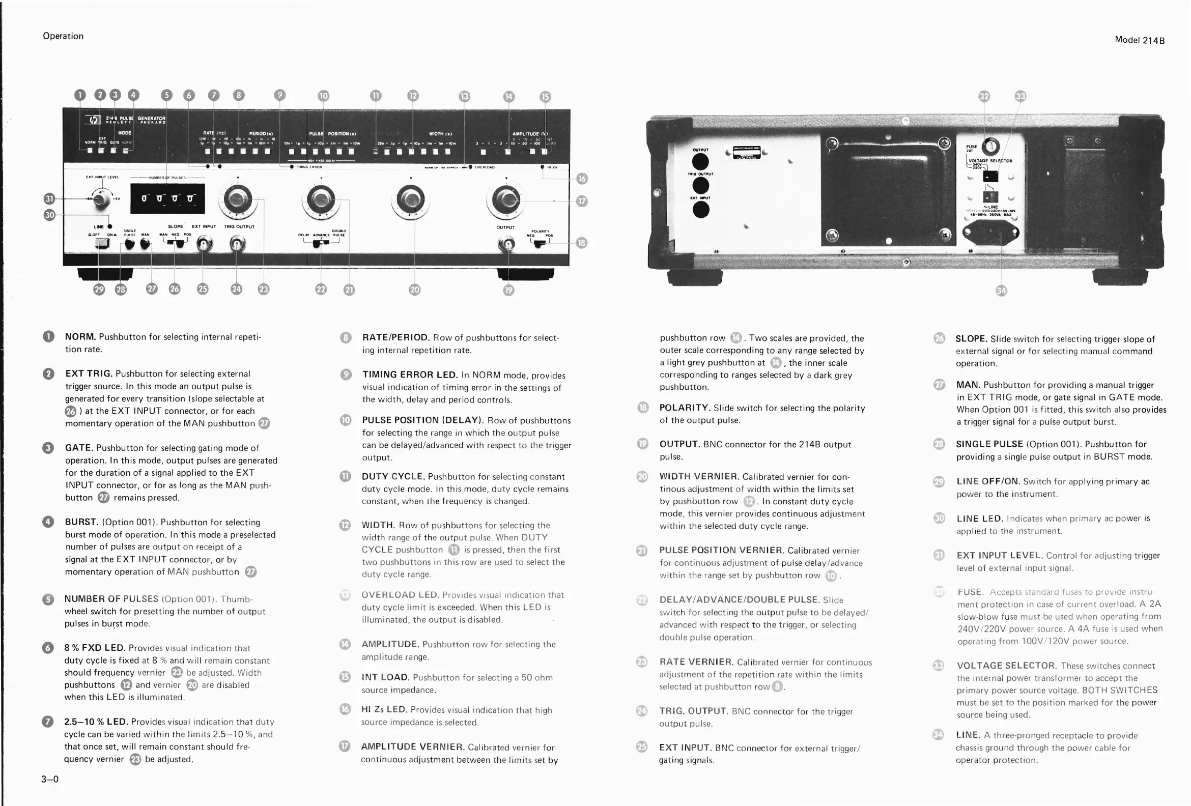
NORM.
Pushbutton
for
selecting internal repeti-
0
RATE/PERIOD
. R
ow
of
pushbuttons
for
select-
pushbutton
row
(D
.
Two
scales
are
provided, the
~
SLOPE. Slide s
wit
ch
for
se
lecti
ng
trigger slope
of
tion
rate.
ing internal repe
tition
rate.
outer
scale corresponding
to
any range selected
by
external signal
or
for
sel
ec
tin
g manual command
a
I
ight
grey
pushbutton
at e, the inner
scale
operation.
0
EXT
TRIG.
Pushbutton
for
selecting external
0
TIMING
ERROR
LED.
In NORM mode, provides corresponding
to
ranges
selected
by
a dark g
re
y
f1I
trigger source. In
this
mode
an
output
pulse
is
v
isua
l indication of
timing
error
in
t
he
se
tt
ings
of
pushbutton.
MAN.
Pushbutton f
or
providing a manual trigger
generated
for
every
transition
(slope selectable at
the
width,
delay and period controls.
in E
XT
TRIG
mode,
or
gate signal in
GATE
mode.
~
)
at
the
EXT
INPUT
connector,
or
for
each
t'D
POLARITY.
Slide switch
for
selecting the
polarity
Wh
en
Option
001 is
fitted,
this switch also provides
momentary
operation
of
the
MAN
pushbutton
f1I
~
PULSE
POSITION
(DELAY).
Row
of
pushbuttons
of
the
output
pulse.
a trigger signal
for
a pulse
out
put burst.
for
selecting the range in which the
output
pul
se
e
GATE.
Pushbutton
for
selecting gating mode
of
c
an
be
delayed/advanced
with
res
pect
to
the
trig
g
er
()
OUTPUT. BNC connector
for
the 214B
output
~
SINGLE
PULSE (Op
tion
001). Pushbutton
for
operation. I n this mode,
output
pulses are generated
out
put.
puls
e.
providing a sin
gl
e pulse
output
in BURST mode.
for
the
duration
of
a signal appl ied
to
the
EXT
0)
DUTY CYCL
E.
Pus
h
butt
on
for
sel
ecting const
ant
e
WIDTH
V E
RNIER.
Calibrated vernier f
or
con-
~
LIN
E O
FF/
ON. Swi
tc
h
for
appl
yi
ng primary
ac
INPUT
connector,
or
for
as
long
as
the
MAN
push-
duty
cycle mode. In
th
is mode, du
ty
cycle remains
tinous
adjustme
nt
of
w
idth
within
the
limi
ts set
power
to the instrument.
button
f1I
remains pressed.
const
ant
, when
th
e frequency is changed.
by
pushbu
tton
row
.
In constant
duty
cy
cle
mode,
th
is
ve
rnier provides
continu
o
us
adjus
tm
ent
e
LIN
E LED. Indicates when
primary
ac
power is
0
BU RST.
(Option
001) . Pushbutton
for
selecting
il
WIDTH.
R
ow
of
pus
hbut
tons
for
se
le
c
tin
g the
with
in
t
he
selected
duty
cycle ran
ge.
appl ied to the instrument.
burst mode
of
opera
tion.
In th
is
mode a preselected
wi
dth r
ange
of
th
e ou
tput
pulse. When
DUTY
number
of
pulses
are
outp
ut on
re
c
eipt
of
a
CYCLE
pushbutton
CD
is
pressed, then the
first
PULSE PO
SIT
ION
VERN
IE
R.
Ca
libr
ated
ve
rnier
EXT
I
NPUT
LEVE
L.
Control
for
adjusting
tr
i
gge
r
signal at the
EXT
IN
PU
T connector,
or
by
two
push
butto
ns in
th
is
row
are
used
to
select
th
e
for
cont inuous adjustment of pulse delay/
ad
vance
level of external
input
signal.
momentary
opera
tion
of
MAN
pushbutto
n
f1I
duty
cycle range.
within
the range set by pushbu
tton
row
OVERLOAD
LED_ Provides
Visual
indication
that
FUSE. Accepts standard tuses to prOVide Instru-
0
NUMBER
OF PULSES
(Option
001).
Thumb-
DELAY/ADVANCE/DOUB
LE
PULSE. Slide
me
nt
protection
in
case
of
current
overload. A
2A
wheel switch
for
pr
es
ettin
g the number of
output
duty
cycle l
imit
is
exceeded. When this LE D
is
sw
itch
f
or
se
lecting t
he
outp
ut
pul
se
to
be
delayed/
slow-blow fuse must
be
used
when operating
from
pulses in
bu~st
mode.
illuminated, the o
utpu
t
is
disabled.
advanced
wi
th
r
espe
ct
to the t r
ig
ger, or selecting
240V
/22
0V
power source. A
4A
fuse
is
used when
e
AMPLITU
D
E.
P
ushbutton
row
fo
r selecting the
double pulse operation.
operating
from
1
OOV
/
120V
power source.
0
8 %
FXD
LED.
Provides
vi
sual
indication
that
duty
cycle
is
fixed
at 8 %
an
d
wil
l remain constant
ampl
it
ude range.
f.I
RATE
VERN
IER.
Cal
ibrated vernier
fo
r
continuous
~
VOLTAGE
SELECTOR
. These switches connect
should frequency vernier
ED
be
adjusted.
Width
G)
INT
LO
AD
_ Pushbutton
for
selecting a 50
ohm
adjustment
of
the
repetition
rate
within
the
limits
the internal power transformer
to
accept the
pushbuttons
il
and vernier e
ar
e disabled
source impedance.
selected at pushbu
tt
on row ;
primary
power
source voltage. BOTH SWITCHES
when this
LED
is
illuminated.
m
us
t
be
set
to
the
position
marked
for
the power
0
HI
Zs
LED.
Provid
es
visual indica
tion
th
at hi
gh
TRIG.
OUTPUT.
BNC connector
for
the trigg
er
source being used.
0
2.5-10
%
LED.
Provides visual indication
that
duty
source impedance
is
se
lected.
out
put
pulse.
~
cycle can
be
varied
withi
n
th
e
limit
s
2.5-
10 %, and
L1NE_
A
thr
ee-pronged recepta
cl
e
to
provide
that
once set,
will
remain constant should
fr
e-
G
AMPLITUDE
VER
NIER
. Calibrated
ve
rnier
fo
r
e
EXT
INPUT. BNC c
onnector
for
external trigger/
ch
ass
is ground
th
rough the
power
cable
for
quency vernier
ED
be
adjusted.
c
ontinuous
ad
jus
tmen
t
be
tween
th
e I im
it
s s
et
by
ga
t ing sign
als.
operator
protecti
on.
3-0
Scans by ArtekMedia => 2009
Digitally signed by ArtekMedia
DN: cn=ArtekMedia, o=ArtekMedia.com, ou, email=manuals@ArtekMedia.com, c=US
Date: 2009.02.18 21:53:38 -06'00'