4. Remove the two Phillips PM2.0×2.0 broad head screws (2) in the optical drive bay that secure
the top cover to the computer.
5. Turn the computer upright with the front toward you and open it.
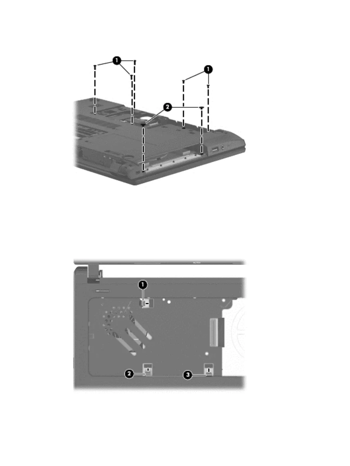
6. Release the following ZIF connectors on the system board:
●
(1): Power button board cable
●
(2): TouchPad button board cable
●
(3): Fingerprint board cable
7. Lift the rear edge of the top cover (1) and swing it up and forward until it detaches from the
computer.
Component replacement procedures 51
 Loading...