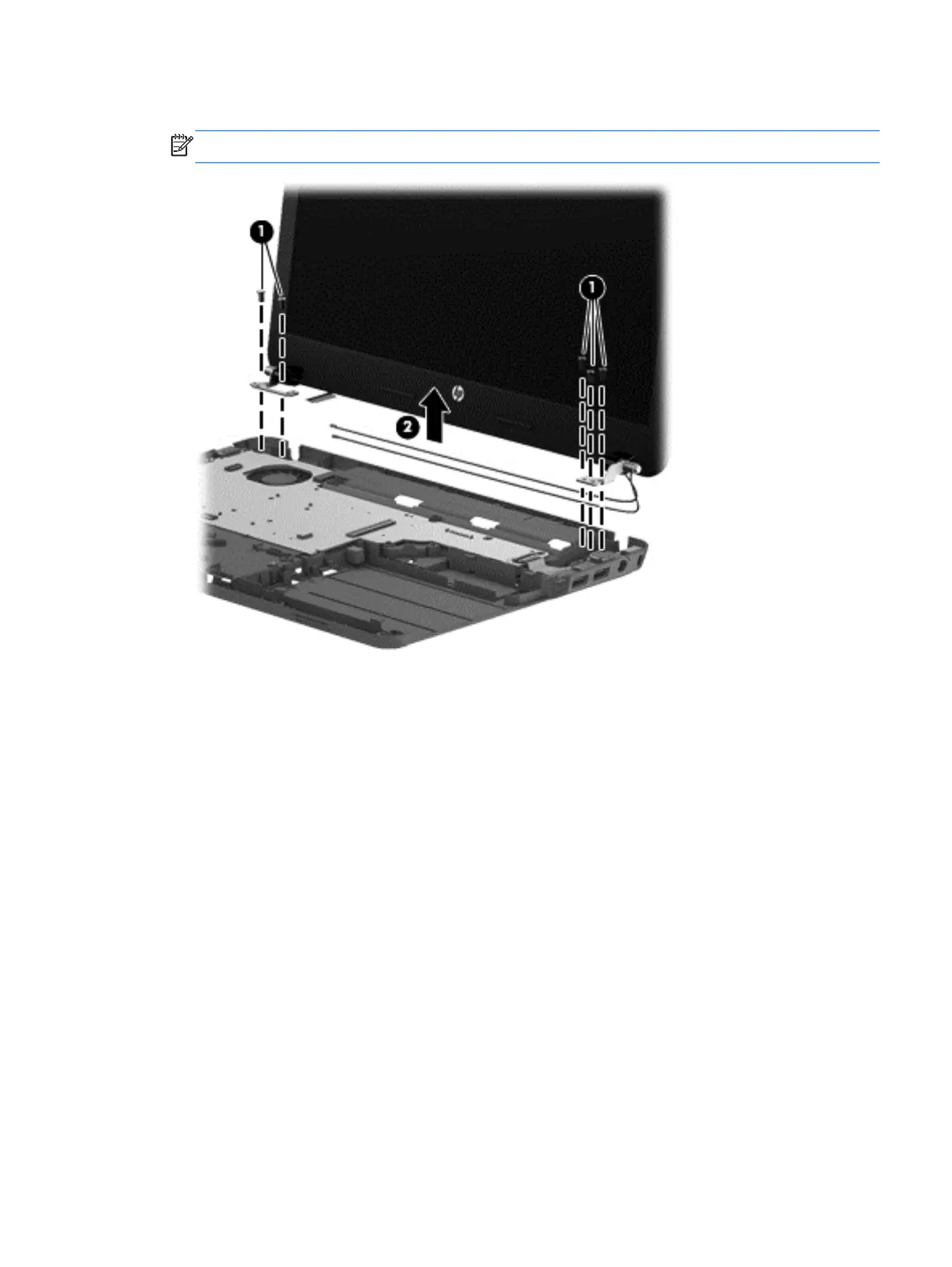
4. Remove the display assembly (2).
NOTE: Models may have either one or two antennas installed.
If it is necessary to replace any of the display assembly subcomponents:
1. To remove the display bezel:
a. Remove the two Mylar screw covers (1) and the two Phillips PM2.5×4.0 screws (2) that
secure the display bezel to the display assembly. The Mylar screw covers are included with
the display bezel spare part kit.
b. Flex the inside edges of the top edge (3), the left and right edges (4), and
the bottom edge (5) of the display bezel until the bezel disengages from the
display enclosure.
Component replacement procedures
95