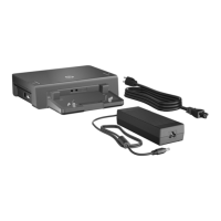
Removal and Replacement Procedures
Maintenance and Service Guide 5–3
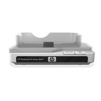
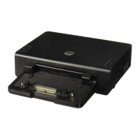
5.2 Disassembly Sequence Chart
Use the chart below to determine the section number to be
referenced when removing docking station components.
Disassembly Sequence Chart
Section Description
# of Screws Removed
5.3 Preparing the Docking Station
for Disassembly
0
5.4 Cable Lock 3 to remove the cable lock
bezel
5.5 Top Cover 3
5.6 Docking LED Board 2
5.7 Hard Drive 4 to remove the hard drive
cover
0 to remove the hard drive
4 to remove the hard drive
bracket
5.8 Fan 2
5.9 Backup Button Board 2
5.10 MultiBay II LED Board 2
5.11 Front Enclosure 11
5.12 Power Button Assembly 2
 Loading...