Section V Model 3300A
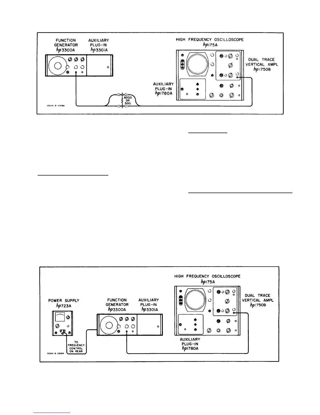
Figure 5-1. 600 ohm or 50 ohm Load Output Test Setup
5-14. Repeat 5-13 on CHANNEL B. Limit should
remain > 15 volts peak-to-peak.
5-15. Repeat 5-13 and 5-14 except load the
instrument with the 50 ohm resistor. CHANNEL A and
CHANNEL B voltage output should be > 2 volts peak-to-
peak.
5-16. SQUARE WAVE RESPONSE.
a. Test equipment required: Oscilloscope (-hp-
Model 175A/1750B) and 10:1 Probe (-hp-
Model 10001A).
b. Connect CHANNEL A OUTPUT without a
load to the oscilloscope using the 10:1
Probe, and set the 3300A controls as
follows:
CHANNEL A function .................SQUARE
FREQUENCY dial ......................10
RANGE switch............................X10K
c. Verify: Rise and fall time <250 nano sec.
Sag <1%
Overshoot (full output) <5%
Symmetry error <1%
5-18. SYNC OUTPUT.
a. Test equipment required: Oscilloscope (-hp-
Model 175A/1750B) and 10:1 Probe (-hp-
Model 10001A).
b. Connect SYNC OUTPUT to oscilloscope
and set 3300A controls as follows:
FREQUENCY dial......................10
RANGE switch ...........................X1K
c. Pulse should be > 10 volts peak-to-peak
and < 5 microsecond duration.
5-19. REMOTE FREQUENCY CONTROL CHECK.
a. Test equipment required: DC Power Supply
(-hp- Model 723A) and Oscilloscope (-hp-
Model 175A/1750B).
CAUTION
VOLTAGE APPLIED TO FREQUENCY
CONTROL BNC SHOULD BE LIMITED
TO A VALUE BETWEEN 0 AND
NEGATIVE 15 VOLTS. VOLTAGES
OUTSIDE THIS RANGE WILL
DAMAGE THE INSTRUMENT.
5-17 Repeat 5-16 on CHANNEL B.
Figure 5-2. Remote Frequency Control Test Setup
5-2