Model 3300A Section V
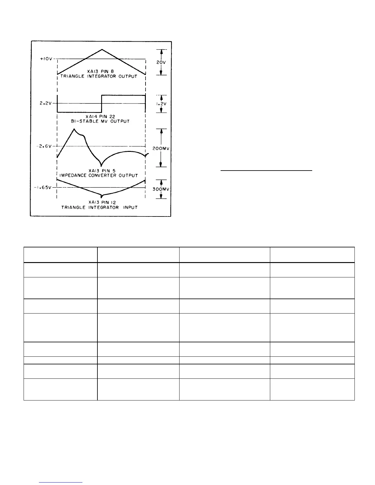
Figure 5-9. Normal Oscillator Wave Forms
limit of the negative slope out of the integrator circuit.
The condition of the other major circuits in the basic
oscillating loop, the Voltage Comparator Bi-stable
Multivibrator and current source, can, in most instances,
be used to isolate the malfunction to a given circuit as
outlined in Figure 5-8. The term normal, as applied to
the results obtained at the different points tested, refers
to the output at that point which would reverse the slope
at the output of the triangle integrator and sustain
oscillation. Abnormal refers to that output which would
produce the same slope and prevent oscillation.
5-61. Figure 5-9 contains the normal voltages and
waveforms which should be present at the points
indicated. Voltage levels are approximate and may vary
from instrument to instrument due to differences in
transistors.
5-62. TROUBLESHOOTING TABLES.
5-63. Table 5-4 gives additional information to assist
in the isolation of a malfunction. Symptoms and
possible causes are listed. Table 5-5, Maintenance
Correlation Table, lists various 3300A functions and
gives the corresponding performance checks and
adjustments.
Table 5-5. Maintenance Correlation Table
ADJUSTMENT AND
FUNCTION PERFORMANCE CHECK CALIBRATION TROUBLESHOOTING
Dial Accuracy Paragraph 5-5 Paragraph 5-34 thru 5-37 Para. 5-23, All assy
Distortion Paragraph 5-7 Paragraphs 5-38, 5-30 and Oven, All assembly
5-31
Output Paragraph 5-10thru 5-15 Paragraphs 5-39 thru 5-42 A15 or A16 assembly
Q5 thru Q8
Square Wave Paragraph 5-16 and 5-17 Paragraph 5-41 and 5-42 Isolate trouble to
specific board or
chassis by interchang-
ing A15 and A16 boards.
Sync Output Paragraph 5-18 None A14C7, A14R46 and
A14R48
Remote Freq control Paragraph 5-19 None J6 or plug-in pins 32, 7
Channel B-A Check Paragraph 5-20 None Continuity A15 pin 11
to S5AF pin 5, 11, to 16R5
Power Supplies None Table 5-2 Remove PC boards; see
Figure 5-4 para. 5-55;Check A12
components
5-10