•
Model 3314A
L. Determine the value of m using the following
equation:
Performance Tests
Specification:
Equipment Required:
where
I:x. I:y. I:xy. I:xI:y, r:x
2,
and
(Ex)2 are the
previously calculated values entered on the performance
test record, and n
= 9 (the number of points to be
calculated).
High Speed Digital Voltmeter
50
Ohm
Feedthrough Termmatron
Tnax
to BNC Connector
Procedures:
M. Determine the value
of
b using the equation:
A. Preset the 3314A.
b = r:y
In
-
mr:x/n
B. Set the 3314A as follows:
N. Calculate the
"best
fit straight line" value for Yo
through
Y9
using the equation:
y=mx+b
Function . . . . . . . . . . . . . . . . . . . . . . . . . . . Triangle
Amplitude.
..
. . , . ,
..
, . , . .
..
..
lOVp-p
Mode
. N Cycle
Trigger
.....
. Negative Edge
Enter each result on the Performance Test Record in the
"Best
Fit Straight
Line"
column.
C. Set the Digital Voltmeter as follows:
O. Algebraically add the voltages recorded in the
"Negative Slope Measurement" column and enter the
total
in the
"I:y"
space.
Range , . , , , . , . . . . . . . .
..
10V
Trigger
.,
,.,
,.".,
Ext
Readings
'.'.'"........
. . . . . . . 1
Delay 0.00025s
P. Repeat steps I through N to determme the
"best
fit straight
line"
values for the negative slope.
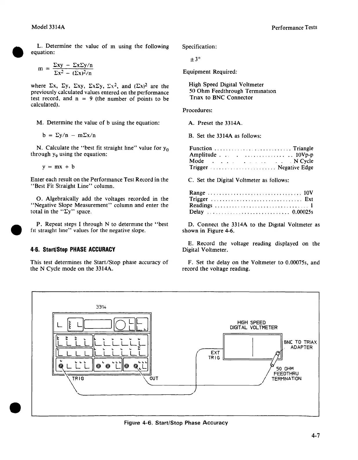
D. Connect the 3314A to the Digital Voltmeter as
shown in Figure 4-6.
4·6.
Start/Stop
PHASE
ACCURACY
E. Record the voltage reading displayed on the
Digital Voltmeter.
This test determines the
Start/Stop
phase accuracy of
the N Cycle mode on the 3314A.
F. Set the delay on the Voltmeter to 0.00075s, and
record
the
voltage reading.
3314
HIGH
SPEED
DIGIT
AL
VOLTMETER
BNC
TO
TRIAX
ADAPTER
/ EXT
~
TRIG
L!:======
F~~g~~RU
/
TERMINATION
-------t-----------,/
~"
......
_---------------~/)
L
[~
LI[
I[OcIEJ
llll
LI
1". l.# .... '*
"-
LLLLLL
..
IL
L L
LI
~
.. .. ..
..
"
LLLLLL
~"""I[""""I~
L L
L~
~
L
~
~
..L
~,
~\=
='
.
Figure
4-6.
Start/Stop
Phase
Accuracy
4-7