PerformanceTests
3314
Model
3314A
AC/DC
DIGITAL
VOLTMETER
"'"
50
OHM
1
"
FEEDTHRu
I uF
-.
TERMINATION
"
-,
,,'-------------------
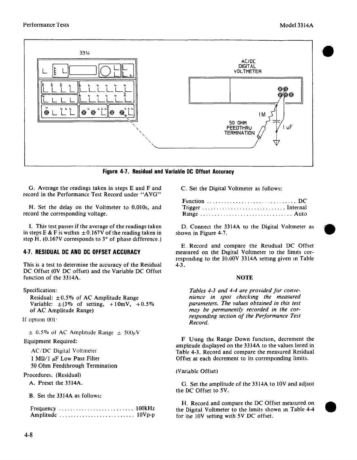
Figure
4·7.
Residual
and
Variable
DC
Offset
Accuracy
O. Average
the
readings
taken
in
steps
E
and
F
and
record in
the
Performance
Test
Record
under
"AVO"
H. Set
the
delay on
the
Voltmeter
to 0.0105,
and
record
the
corresponding
voltage.
I.
This test passes
if
the
average
of
the
readings
taken
in steps E & F is
within
± 0.167V
of
the
reading
taken
in
step H. (O.167V
corresponds
to 3°
of
phase
difference.)
4·7.
RESIDUAL
DC
AND
DC
OFFSET
ACCURACY
This is a test to determine
the
accuracy
of
the
Residual
DC
Offset
(OV
DC offset)
and
the
Variable
DC Offset
function
of
the
3314A.
Specification:
Residual:
±O.507o
of
AC
Amplitude
Range
Variable:
±(3%
of
setting, + 10mV,
+0.5%
of
AC
Amplitude
Range)
If
opnon
001'
±
0.5%
of
AC
Amplitude
Range ± 500pV
Equipment
Required:
AC/DC
Digital Voltmeter
1
MOil
p.F Low
Pass
Filter
50
Ohm
Feedthrough
Termination
Procedures; (Residual)
A.
Preset
the
3314A.
B. Set the 3314A as follows:
Frequency
".,.,
,
..
, , . , , . , , .
..
100kHz
Amplitude
"
..
" ,
..
""
..
"
,.
IOVp-p
4-8
C,
Set
the
Digital Voltmeter as follows:
Function
..
, . , , , , ,
..
, . , . - - - -
..
, ,
..
,
..
DC
Trigger , . , , , . , , , , , , , ,
Internal
Range , , , . , . , . , . , , , ,
Auto
D.
Connect
the
3314A to
the
Digital
Voltmeter
as
.~
shown in Figure 4-7,
.,
E.
Record
and
compare
the
Residual
DC
Offset
measured on
the
DIgital
Voltmeter
to
the
lirmts cor-
responding to the
lO.ODV
3314A
settmg
given m
Table
4-3.
NOTE
Tables 4-3 and 4-4 are provided
for
conve-
nience in spot checking the measured
parameters. The values obtained in this test
may be permanently recorded in the cor-
responding section
of
the Performance Test
Record.
F Using the
Range
Down
function,
decrement
the
amplitude displayed on
the
3314A to
the
values listed in
Table 4-3.
Record
and
compare
the
measured
Residual
Offset at
each
decrement to its
corresponding
limits.
(Variable Offset)
G,
Set
the
amplitude
of
the
3314A to IOV
and
adjust
the
DC
Offset
to 5V.
H,
Record
and
compare
the
DC
Offset
measured
on
the
Digital Voltmeter to
the
hmits
shown
in
Table
4-4
for
the lOV settmg WIth 5V DC offset.