Model 3314A
Performance Tests
SYNTHESIZERf
FUNCTION
GENERA
TOR
SPECTRUM
ANALYZER
o
~
~
l.':=============;/!::::==::::!J
/
500
INPUT
,\_~---------------~,/
'\AM
\
\,
\
\
\
\
\
'"
_~
II
\
~/~50
OHM
\
~
FEEDTHRU
~---------------
TERMINATION
3314
[gl
lIe)
~IEJ
L
[lLL
LI
~
L
~
~
~
v
LLLLLL
"
[L L L
LI
~ ~
~
v L
LLLLLL
[WL
L~
L
l~
v
@»
~
LI[~
~~g
, ,
\
,,"=
Procedures:
A. Preset the the 3314A.
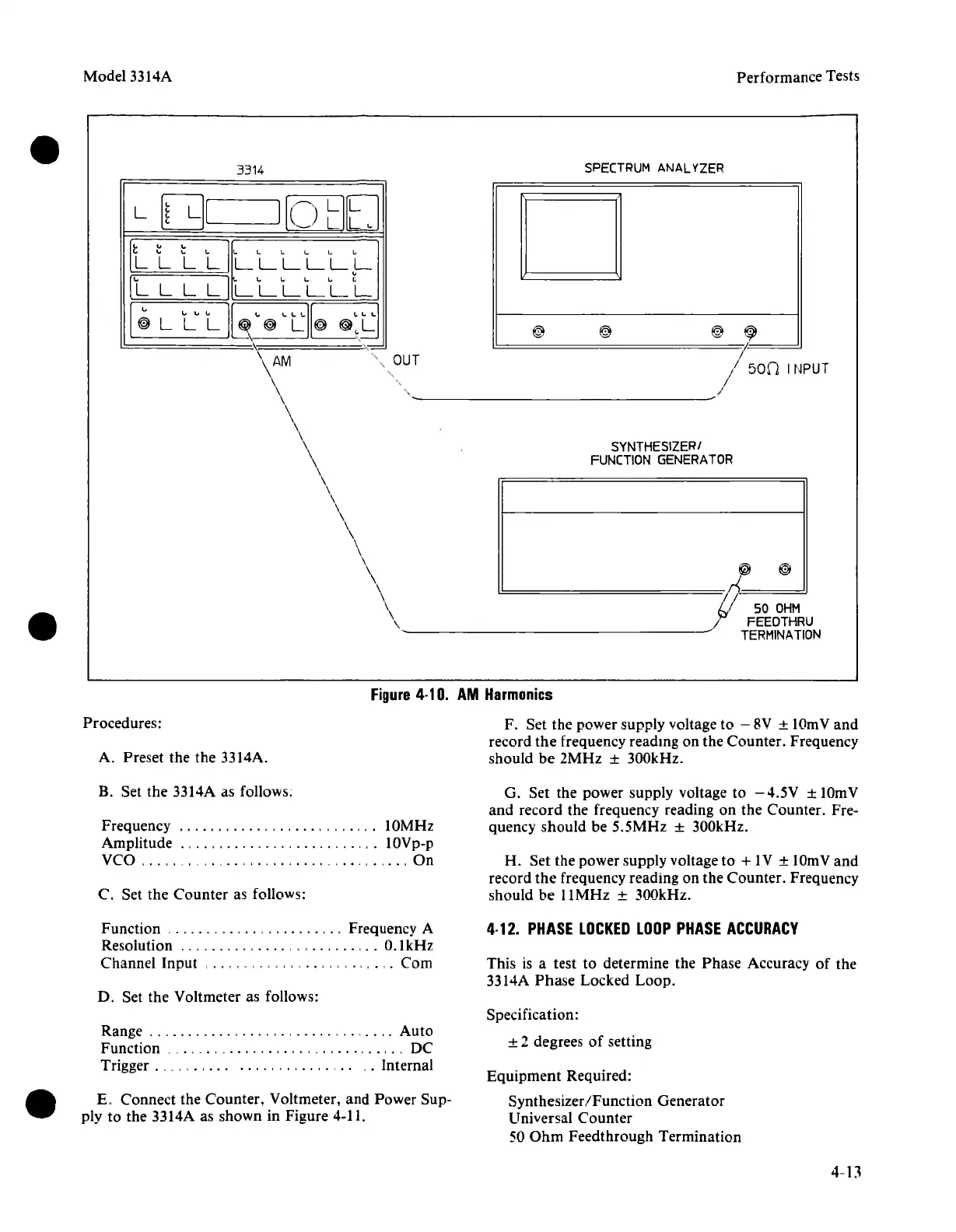
Figure
4·10.
AM
Harmonics
F. Set the power supply voltage to - 8V ± 10mV and
record the frequency reading on the Counter. Frequency
should be 2MHz
± 300kHz.
B. Set the 3314A as follows;
Frequency
" , ,
,.
lOMHz
Amplitude
.,
,.,
,
.,
lOVp-p
VCO
_. _
..
_ _ , On
C. Set the Counter as follows:
G. Set the power supply voltage to
-4.5V
± lOmV
and record the frequency reading on the Counter. Fre-
quency should be 5.5MHz
± 300kHz.
H. Set the power supply voltage to
+1V ± 10mVand
record
the
frequency reading on the Counter. Frequency
should be 11MHz
± 300kHz.
Function
".,
..
,
,.,
Frequency A
Resolution
, ' , ,
..
O.lkHz
Channel Input
,
..
, -, , , , ,
..
, , . " Com
D. Set the Voltmeter as follows:
4·12.
PHASE
LOCKED
LOOP
PHASE
ACCURACY
This is a test to determine the Phase Accuracy of the
3314A Phase Locked Loop.
Range
..
, , '" Auto
Function
__
..
_
..
_ _. . . . . . . . .
..
DC
Trigger .
__
. . . . .
..
..,
,
,....
.,
Internal
K Connect the Counter, Voltmeter, and Power Sup-
ply to the 3314A as shown in Figure 4-11.
Specification:
± 2 degrees
of
setting
Equipment Required:
Synthesizer
IFunction Generator
Universal Counter
50
Ohm
Feedthrough Termination