Performance Tests
Model 3314A
SINE
WAVE
HARMONICS
Equipment Required:
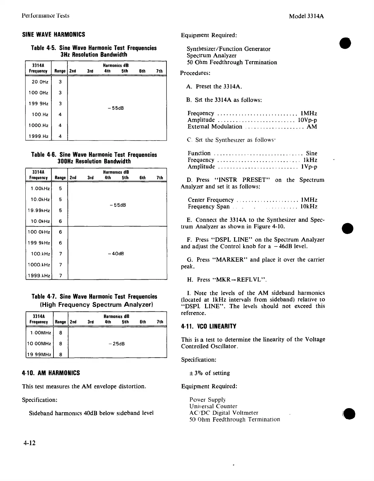
Table
4·5.
Sine
Wave
Harmonic
Test
Frequencies
3Hz
Resolution
Bandwidth
3314A
Harmonics
dB
Frequency
Range
2nd
3rd
4th 5th
6th 7th
200Hz
3
1000Hz
3
1999Hz
3
- 55dB
100Hz
4
10000Hz 4
1999Hz
4
SynthesizerIFunction Generator
Spectrum Analyzer
50 Ohm Feedthrough Termination
Procedures:
A. Preset the 3314A.
B, Set the 3314A as follows:
Frequency
..
, , . , , "
IMHz
Amplitude . 0
..••.
0 , . ,
••.•.•
, • 0
•.
lOVp-p
External Modulation
. 0. 000
..•
,
..•.••.
, • AM
C Set the Synthesizer as follows'
H. Press
"MKR-REFLVL".
E. Connect the 3314A to the Synthesizer
and
Spec-
trum Analyzer as shown in Figure 4-10.
F. Press
"DSPL
LINE"
on the Spectrum Analyzer
and adjust the Control knob for a -
46dB level.
D. Press
"INSTR
PRESET"
on the Spectrum
Analyzer and set it as follows:
,
..
IMHz
10kHz
Center Frequency
.
Frequency Span _
Function
0
•••••
0 • ,
••
-
•••••••••••••
_ • ,
,.
Sine
Frequency.
, , , . , _.
,,1kHz
Amplitude
..
""
..
,
..
,.,
..
,."
..
,
..
" IVp-p
G. Press
"MARKER"
and
place it over the carrier
peak.
Table
4·6.
Sine
Wave
Harmonic
Test
Frequencies
300Hz
Resolution
Bandwidth
3314A
Harmonics
dB
Frequency
Range
2nd 3rd 4th 5th
6th 7th
100~Hz
5
1000kHz
5
-55dB
19099kHz
5
100kHz
6
1000kHz
6
1999kHz
6
100,kHz
7
-40dB
10000kHz 7
1999o~Hz
7
Table
4·7.
Sine
Wave
Harmonic
Test
Frequencies
(High
Frequency
Spectrum
Analyzer)
3314A
Harmonics
dB
Frequency
Range
2nd 3rd 4th 5th 6th 7th
100MHz
8
1000MHz
8
-25dB
1999MHz
8
I. Note the levels of the AM sideband harmonics
(located at 1kHz intervals from sideband) relative to
"DSPL
LINE".
The
levels should
not
exceed this
reference.
4·11.
VCO
LINEARITY
This is a test to determine the linearity of the Voltage
Controlled Oscillator.
Specification:
4·10.
AM
HARMONICS
±
3070
of
setting
This test measures the AM envelope distortion.
Equipment Required:
Specification:
Sideband harmonics 40dB below sideband level
Power Supply
Universal Counter
ACiDC
Digital Voltmeter
50 Ohm Feedthrough Termination
4-12