Model 3314A
Performance Tests
3314
INPUT
INPUT
A
B
00
@
@~
@)@I
Ii
Ii
UNIVERSAL
COUNTER
50
OHM
I I I I 50
OHM
FEEDTHRU
1;/ 1;/
FEEDTHRU
TERMINA
TION
I I
TERMINA
TION
I
~---------------
'\
OUT
'-
[GI
L
I[(~)
LIEJ
--
L L
~
IL
II
LI
L IJ \.. ... ...
LLLLLL
~
It
L L
LI
Lv....
\..
....
tI
LLLLLL
[;
~
~ ~
II
~ ~ ~
~I~
L L
L@
@I
L e
~L
=\
\=
SYNTHESIZERI
FUNCTION
GENERA
TOR
•
~~
@
~
..J
-a,
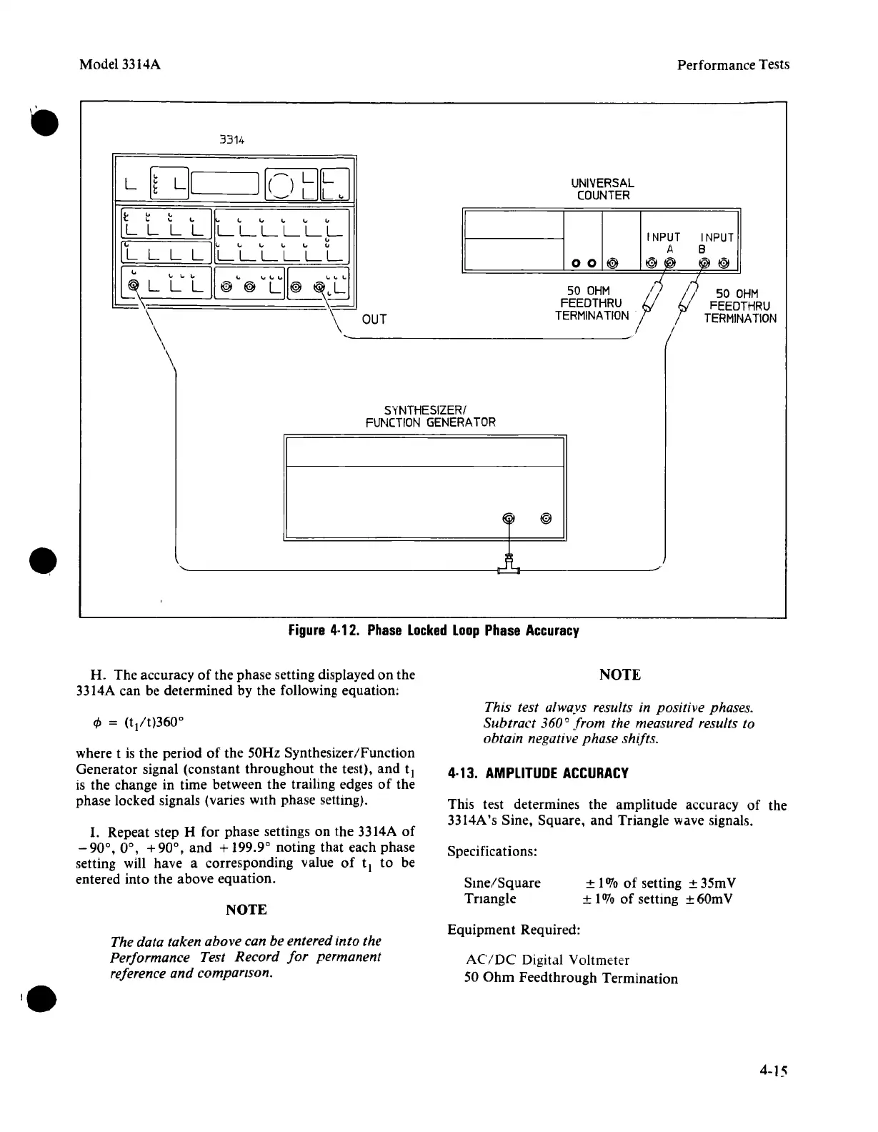
Figure
4·12.
Phase
Locked
Loop
Phase
Accuracy
NOTE
4·13.
AMPLITUDE
ACCURACY
This test determines the amplitude accuracy
of
the
3314A's Sine, Square,
and
Triangle wave signals.
±
1010
of
setting ± 35mV
± 1%
of
setting ± 60mV
This test always results in positive phases.
Subtract 360
0
from the measured results to
obtain negative phase shifts.
Sine/Square
Tnangle
Specifications:
NOTE
H.
The accuracy
of
the phase setting displayed on the
3314A can be determined by the following equation:
where t is the period
of
the 50Hz Synthesizer/Function
Generator signal (constant
throughout
the test),
and
t
l
is the change in time between the trailing edges
of
the
phase locked signals (varies with phase setting).
I.
Repeat step H for phase settings on the 3314A
of
- 90°,
0°,
+90°,
and
+ 199.9° noting that each phase
setting will have a corresponding value
of
t
l
to be
entered into the above equation.
The data taken above can be entered into the
Performance Test Record
for
permanent
reference and comparison.
Equipment
Required:
AC/DC
Digital Voltmeter
50
Ohm
Feedthrough Termination
4-15