Performance Tests
Model 3314A
3314
AC/OC
DIGITAL
VOLTMETER
~@
II
/
/
I
50
OHM
\\
OUT /
FEEOTHRU
"-'<-------------------/
TERMINA
TION
L
Ell
1[0
u:
[L
II
LI
~ ~ ~
~ ~
LLLLLL
[L L L
LI
(" "" "" l". ""
~
LLLLLL
[ u u
~
u
II
u v
HI~
~
L L L
~
~
L
@)
~
..L
\--=
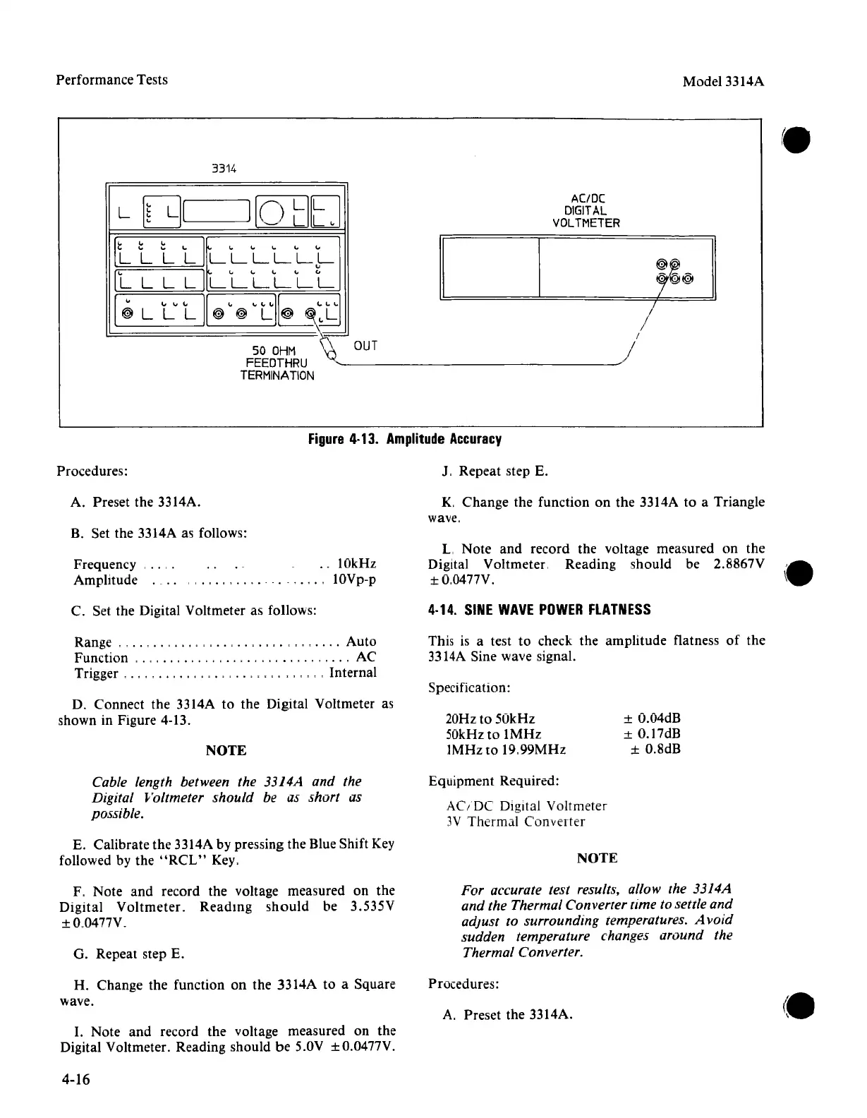
Figure
4·13.
Amplitude
Accuracy
Procedures:
J. Repeat step E.
A. Preset the 3314A.
K.
Change
the function on
the
3314A to a Triangle
wave.
B. Set the 3314A as follows:
Frequency .
Amplitude .
..
10kHz
lOVp-p
L
Note
and
record the voltage measured on
the
Digital Voltmeter. Reading should be 2.8867V
±O,0477V.
C. Set
the
Digital Voltmeter as follows:
4·14.
SINE
WAVE
POWER
FLATNESS
This is a test to check
the
amplitude
flatness
of
the
3314A Sine wave signal.
Range
, ,
..
, , , ,
..
,
..
, ,
Auto
Function
,.,
, . , . ,
....
, , , , , , ,
..
, AC
Trigger
, . , , ,
..
, , , , , , Internal
D. Connect
the
3314A to
the
Digital Voltmeter as
shown in Figure 4-13.
NOTE
Specification:
20Hz to
50kHz
50kHz
to
IMHz
IMHz
to
19.99MHz
± O.04dB
± O.17dB
± O.8dB
Cable length between the 3314A and the
Digital Voltmeter
should be as short as
possible.
Equipment Required:
AC/DC
Digital Voltmeter
3V Thermal
Converter
E. Calibrate the 3314A by pressing the Blue Shift Key
followed by
the
"RCL"
Key.
NOTE
F, Note
and
record the voltage measured on the
Digital
Voltmeter.
Reading
should
be 3.535V
±O.0477V.
G. Repeat step E.
For accurate test results, allow the 3314A
and the Thermal Converter time to settle and
adjust
to surrounding temperatures. A void
sudden temperature changes around the
Thermal Converter.
H.
Change
the
function on the 3314A to a Square
wave.
Procedures:
A. Preset the 3314A.
I. Note
and
record
the
voltage measured on the
Digital Voltmeter. Reading should
be
5.0V ± O.0477V.
4-16