Model 3314A
Performance Tests
SPECTRUM
ANALYZER
500
INPUT
o
VHF
ATTENUATOR
OUT \ /
\ /
\~--iill--
~//
T
3314
[~
Ljl
ll(~)
LIE]
L
- L
L~
IL
L L
LI
"-
l.
... "" l.>
LLLLLL
IL
L L
LI
"
""
l.
1,., .... l. l.J
LLLLLL
I
~
~
~ ~
II
~
"c
cl~
~
L L L
~
@I
L
@I
~~L
\~
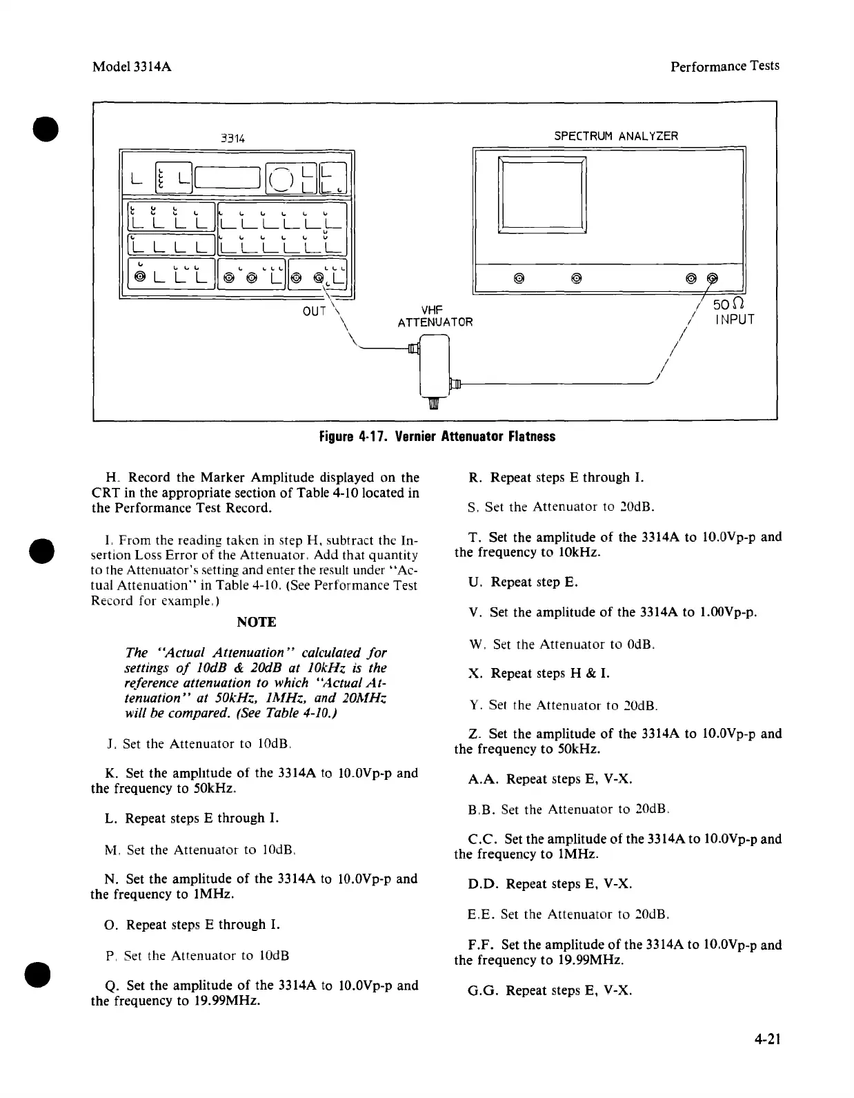
Figure
4·17.
Vernier
Attenuator
Flatness
K Record the Marker Amplitude displayed on the
CRT in the appropriate section
of
Table 4-10 located in
the Performance Test Record.
R. Repeat steps E through
I.
S. Set the Attenuator to 20dB.
L
From
the reading taken in step H, subtract the In-
sertion Loss
Error
of the Attenuator. Add that quantity
to the Attenuator's setting and enter the result under "Ac-
tual
Attenuation"
in Table 4-10. (See Performance Test
Record for example.)
NOTE
T. Set the amplitude of the 3314A to
1O.OVp-p
and
the frequency to 10kHz.
U. Repeat step E.
V. Set the amplitude of the 3314A to l.OOVp-p.
The "Actual Attenuation" calculated
for
settings
of
lOdB & 20dB at 10kHz is the
reference attenuation to which "Actual
At-
tenuation" at 50kHz, 1MHz, and 20MH..
will be compared. (See Table 4-10.)
W, Set the
Attenuator
to OdB,
X. Repeat steps H &
I.
Y. Set the Attenuator to
20dR
J. Set the Attenuator to lOdls.
Z. Set the amplitude
of
the 3314A to 1O.0Vp-p and
the frequency to 50kHz.
K. Set the amplitude
of
the 3314A to
1O.OVp-p
and
the frequency to 50kHz.
A.A.
Repeat steps E. V-X.
L. Repeat steps E through
I.
RB.
Set the Attenuator to 20dB.
M, Set the Attenuator to 10dB.
C.C.
Set the amplitude of the 3314A to 1O.0Vp-p
and
the frequency to 1MHz.
N. Set the amplitude
of
the 3314A to 10.0Vp-p and
the frequency to 1MHz.
D.O.
Repeat steps E. V-X.
O. Repeat steps E through
I.
E,E.
Set the Attenuator to 20dB.
P, Set the Attenuator to lOdB
F.F.
Set the amplitude
of
the 3314A to 1O.0Vp-p
and
the frequency to 19.99MHz.
Q. Set the amplitude
of
the 3314A to
1O.OVp-p
and
the frequency to 19.99MHz.
G.G.
Repeat steps E. V-X.
4-21