Model 3314A
Performance Tests
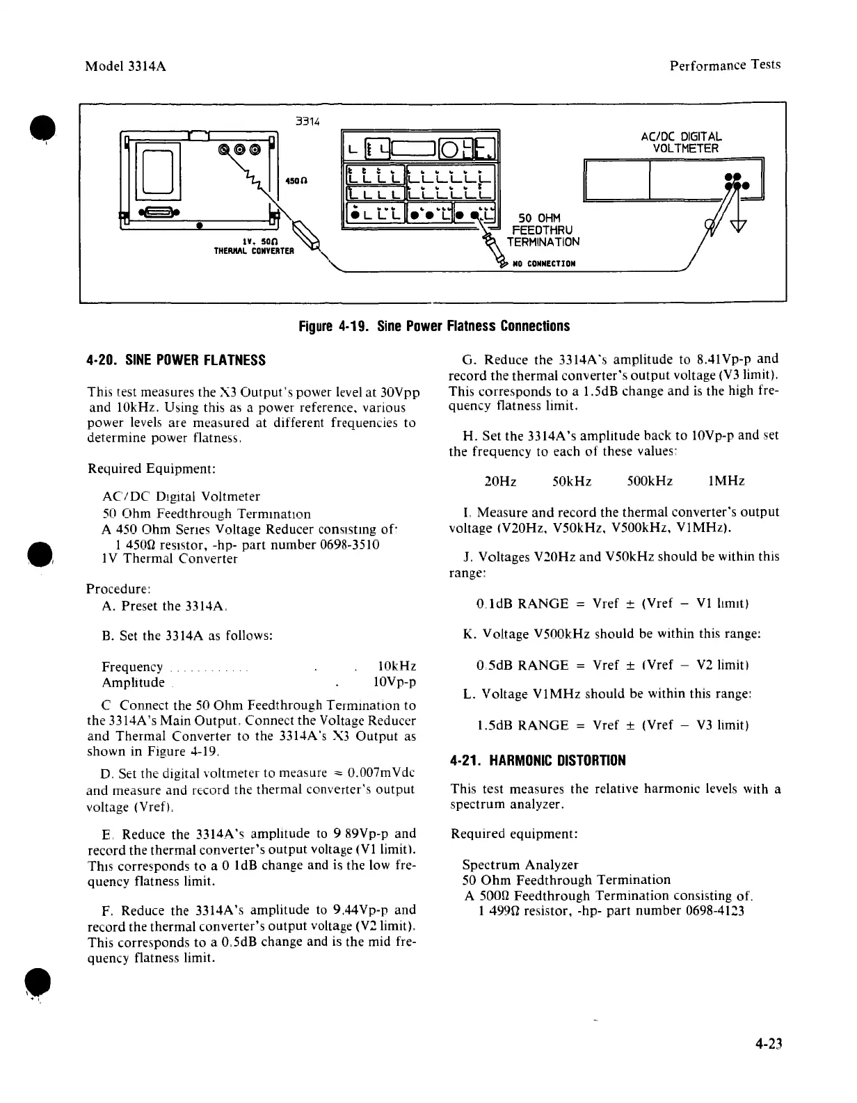
3314
AC/DC
DIGITAL
VOLTMETER
\
50
OHM
FEEDTHRU
TERMINA
TION
NO
CONNECTI
ON
L~LII
110
HtL
III
ttl
LLLLLL
11
L L L
to '" '" '" r
LLLLLL
I·LLL~~~:!j
[]
Figure
4-19.
Sine
Power
Flatness
Connections
4-20.
SINE
POWER
FLATNESS
This test measures the X3
Output's
power level at 30Vpp
and
10kHz. Using this as a power reference. various
power levels are measured at different frequencies to
determine power flatness. -
G. Reduce
the
3314A's amplitude to 8,41Vp-p and
record the thermal converter's
output
voltage (V3 limit).
This corresponds to a 1.5dB change and is the high fre-
quency flatness limit.
H. Set the 3314A's amplitude back to 10Vp-p and set
the
frequency to each
of
these values:
Required Equipment:
20Hz
50kHz
500kHz
1MHz
AC/DC
Digital Voltmeter
50 Ohm Feedthrough Terrnmation
A 450
Ohm
Serres Voltage Reducer consisting
of'
1 4500 resistor, -hp-
part
number 0698-3510
1V Thermal Converter
Procedure:
A. Preset the 3314A.
L Measure
and
record the thermal converter's
output
voltage (V20Hz. V50kHz, V500kHz, V1MHz).
J. Voltages
V20Hz
and
V50kHz should be within this
range:
o 1dB
RANGE
= Vref ± (Vref - VI lumtj
B. Set the 3314A as follows:
K. Voltage V500kHz should be Within this range:
•
."
Frequency 10kHz
Amplitude IOVp-p
C Connect the 50
Ohm
Feedthrough Termination to
the
3314A's Main
Output.
Connect
the
Voltage Reducer
and
Thermal Converter to the 3314A's X3
Output
as
shown in Figure 4-19.
D, Set the digital voltmeter to rneasure
ve 0.007mVdc
and
measure and record the thermal converter's
output
voltage (Vref').
E. Reduce the 3314A's amplitude to
989Vp-p
and
record the thermal converter's
output
voltage (VI limit).
This corresponds to a 0 1dB change and is the low fre-
quency flatness limit.
F. Reduce the 3314A's amplitude to 9.44Vp-p
and
record the thermal converter's
output
voltage (V2 limit).
This corresponds to a O.5dB change and is the mid fre-
quency flatness limit.
O,5dB
RANGE
= Vref ± (Vref - V2 limit)
L. Voltage
V1MHz
should be within this range:
1.5dB
RANGE
= Vref ± (Vref - V3 limit)
4-21.
HARMONIC
DISTORTION
This test measures the relative harmonic levels with a
spectrum analyzer.
Required equipment:
Spectrum Analyzer
50
Ohm
Feedthrough Termination
A
500n Feedthrough Termination consisting of.
1 499U resistor, -hp-
part
number
0698-4123
4-23


 To Next Page