SECTION
V
ADJUSTMENTS
5·1.
INTRODUCTION
The
adjustmen
t
and
measurement procedures
conta
ined
in this section are intended to restore the 3314A to its
optimum
operat
ing condition. Adjustment
of
the instru-
ment is necessary following repair, replacement
of
com-
ponents,
or
if desired,
after
the instrument has failed a
Performance
Test. These procedures should also be
followed for periodic maintenance
of
the instrument,"
The
fol1owing tests were developed using the
equipment
listed in Section I
of
this
manual.
Equipment with equal
9
'"
....
etter critical specifications may be used; however, the
c .
.ator
is responsible for the determination
of
accurate
t~st
results. See Section VII, Manual Backdating, for
"A"
(
lanations.
The
individual
adjustments
and
measurements should be completed in the order in which
they
are
presented.
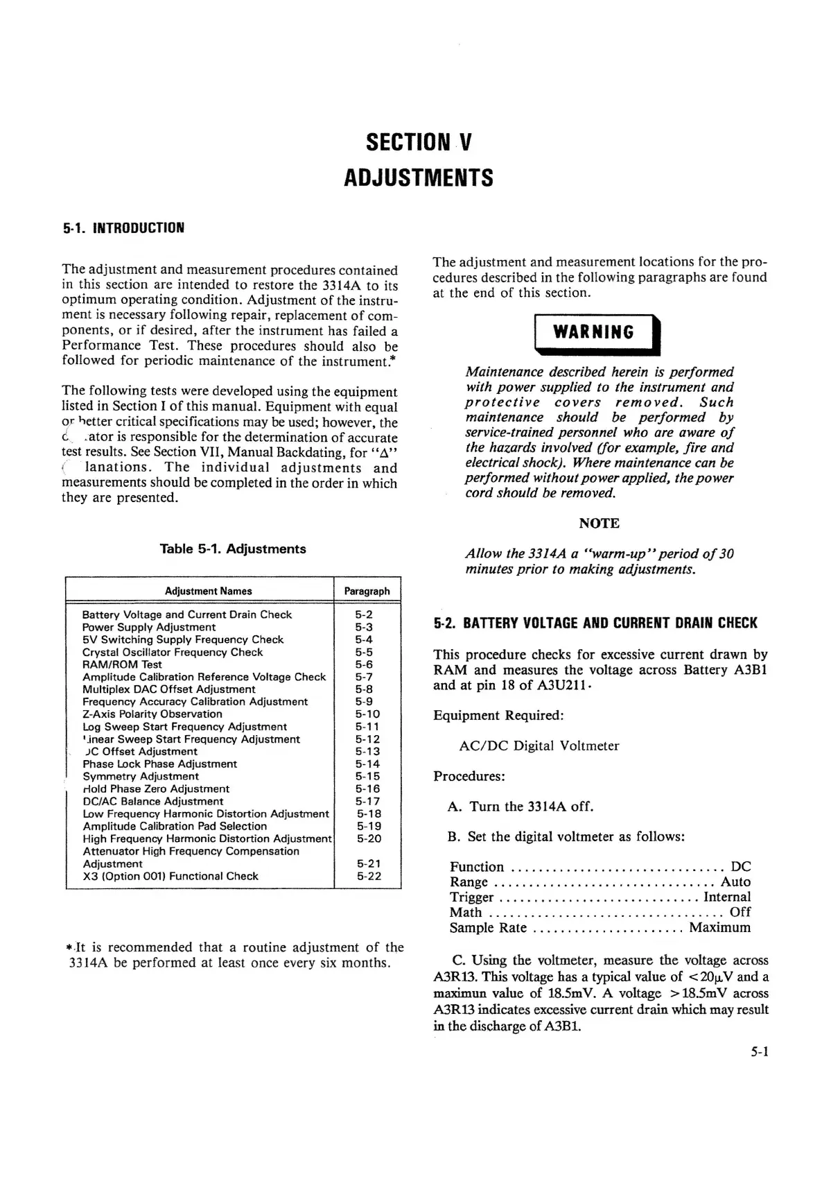
Table 5-1.
Adjustments
Adjustment Names
Paragraph
Battery
Voltage and
Current
Drain
Check
5-2
Power
Supply
Adjustment
5-3
5V
Sw
itch
ing
Supply
Frequency
Check
5-4
Crystal
Oscillator
Frequency
Check
5-5
RAM/ROM
Test 5-6
Amplitude
Calibration Reference Voltage
Check
5-7
Multiplex
DAC
Offset
Adjustment
5-8
Frequency
Accuracy
Calibration
Adjustment
5-9
Z-Axis
Polarity
Observation
5-10
Log
Sweep
Start
Frequency
Adjustment
5-11
l-inear
Sweep
Start
Frequency
Adjustment
5-12
)C
Offset
Adjustment
5
-13
Phase Lock Phase
Adjustment
5-14
Symmetry
Adjustment
5-15
Hold
Phase Zero
Adjustment
5-16
DC/AC Balance
Adjustment
5-17
Low Frequency
Harmonic
Distortion
Adjustment
5-18
Amplitude
Calibration Pad Selection 5
-19
High Frequency
Harmonic
Distortion
Adjustment
5-20
Attenuator
High Frequency
Compensation
Ad
justment
5-21
X3
(Opt
ion 001)
Funct
ional
Check
5-22
*.It is recommended
that
a routine adjustment
of
the
3314A be
performed
at least once every six months.
The
adjustment and measurement locations for the pro-
cedures described in the following
paragraphs
are found
at the end
of
this section.
WARNING
I
Maintenance described herein is performed
with power supplied to the instrument and
protective
covers
removed.
Such
maintenance should be performed by
service-trainedpersonnel who are aware
of
the hazards involved (for example, fire and
electricalshock). Where maintenance can be
performed without power applied, thepower
cord should be removed.
NOTE
Allow the 3314A a "warm-up" period
of
30
minutes prior to making adjustments.
5·2.
BATIERY
VOLTAGE
AND
CURRENT
DRAIN
CHECK
This procedure checks for excessive
current
drawn by
RAM
and
measures the voltage across Battery A3Bl
and
at pin 18
of
A3U211·
Equipment
Required:
AC/DC
Digital Voltmeter
Procedures:
A.
Turn
the 3314A
off.
B. Set
the
digital voltmeter as follows:
Function
DC
Range
Auto
Trigger Internal
Math
Off
Sample
Rate
Maximum
C. Using the voltmeter, measure
the
voltage across
A3R13. This voltage has a typical value of
<
20f.L
V and a
maximun value of 18.5mV. A voltage
> 18.5mV across
A3R13 indicates excessive current
drain
which may result
in the discharge of A3B1.
5-1


 To Next Page
 Loading...