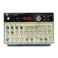
Model 3314A
5·4. 5V
SWITCHING
SUPPLY
FREQUENCY
CHECK
This procedure measures the Switching Frequency
of
the +5VDC supply.
Equipment Required:
Universal Counter
10:1
Probe
Procedures:
A. Preset the 3314A.
B. Set the counter as follows:
Function Freq A
Resolution , 1Hz
Level A Preset
Slope
+
Coupling AC
Attenuation
xl0
Input Termination . . . . . . . . . . . . . . . . . . .
..
1 MO
Sample Rate Adjust CCW
as necessary
C. Using the probe, measure the Switching frequency
at the collector
of
A3Q108. The frequency should be
33kHz
± 303kHz.
NOTE
Note that this is the "average" value and
that instantaneous deviations greater than
the 10% spread may occur.
If
the measured
frequency remains outside the 33kHz
±3.3kHz
range, suspect hardwareproblems
or a possible short
of
the
+5V
supply.
Adjustments
5·5.
CRYSTAL
OSCILLATOR
FREQUENCY
CHECK
This procedure measures the Crystal Oscillator frequen-
cy.
Equipment Required:
Universal Counter
Procedures:
. A. Preset the 3314A.
B. Set the counter as follows:
Function . . . . . . . . . . . . . . . . . . . . . . . . . . . . Freq A
Resolution . . . . . . . . . . . . . . . . . . . . . . . . . . .
..
1Hz
Level A Preset
Slope
+
Coupling AC
Attenuation x
I
Input Termination 1 MO
Sample Rate Adjust CCW
as necessary
C. Using the counter, measure the Crystal Oscillator
frequency at A3TP5 (MPU CLK
I)
and
A3TP4 (MPU
CLK
2). The frequency should be 1.0MHz ± 50Hz.
NOTE
If
the frequency measured in step C is out-
side the given range by 10% or more, the
crystal may have to be replaced.
5·6.
RAM/ROM
TEST
This procedure checks for
RAM
or ROM failures within
the 3314A
and
tests the functioning
of
the front panel
keys.
Equipment Required:
NONE
Procedures:
A.
Turn
the
3314A
OFF,
then
ON,
while
simultaneously pressing the
"ARB"
key.
5-3


 To Next Page