Adjustments
~11
Table
5·2.
RAM/ROM
Location
and
Reference
LED's
ROM
Test
LED
FREQ
AMPTD
OFFSET
SYM
PHASE
N
Reference
U20 8
U208 U207
U207
U207
U207
Designator
ROM
Address
4000
-
6000-
8000-
AOOO
-
COOO
-
EOOO
-
B
lock
5FFF
7FFF
9F
FF
BOOO
0000
FFFF
RAM
Test
SW/TR
I
START
I
STOP
I
LED
INTVL
FRED FRED
MKR
Reference
U211
Designator
B.
After
power has been restored to the 3314A,
release
the
"ARB"
key.
C.
The
3314A front panel will be blank for approx-
imately 30 seconds while the
RAM/ROM
Test is in
Pro-
gress. At the
end
of
this period, all front panel
LED'S
and
display segments should illuminate.
D.
RAM
or ROM failures are indicated by the non-
illumination
of
the
LED
corresponding to the
selected
front
panel parameter listed in Table 5-2.
For
example,
if
ROM
add
ress block 6000-7FFF failed, the "
AMPTD
"
LED
would not illuminate indicating a
bad
U208.
NOTE
Should a
LED
assigned to the
RAM/ROM
locations fail to illuminate, press its cor-
responding key.
If
the
LED
illuminates when
the key is pressed, then the
RAM
or
ROM
is
probably bad.
If
the
LED
does not il-
luminate when the key
is pressed, then the
LED
is most likely defective.
E.
After
replacing any failed
RAM
or ROMs, repeat
test beginning with step A to verify the quality
of
any
new parts. Repeat this test until all RAM
and
ROM LEDs
illuminate without a failure then proceed to step F.
F.
After
determining
RAM/ROM
quality, press each
front panel key
and
verify
that
its corresponding
LED
toggles. This assures
that
each key functions properly.
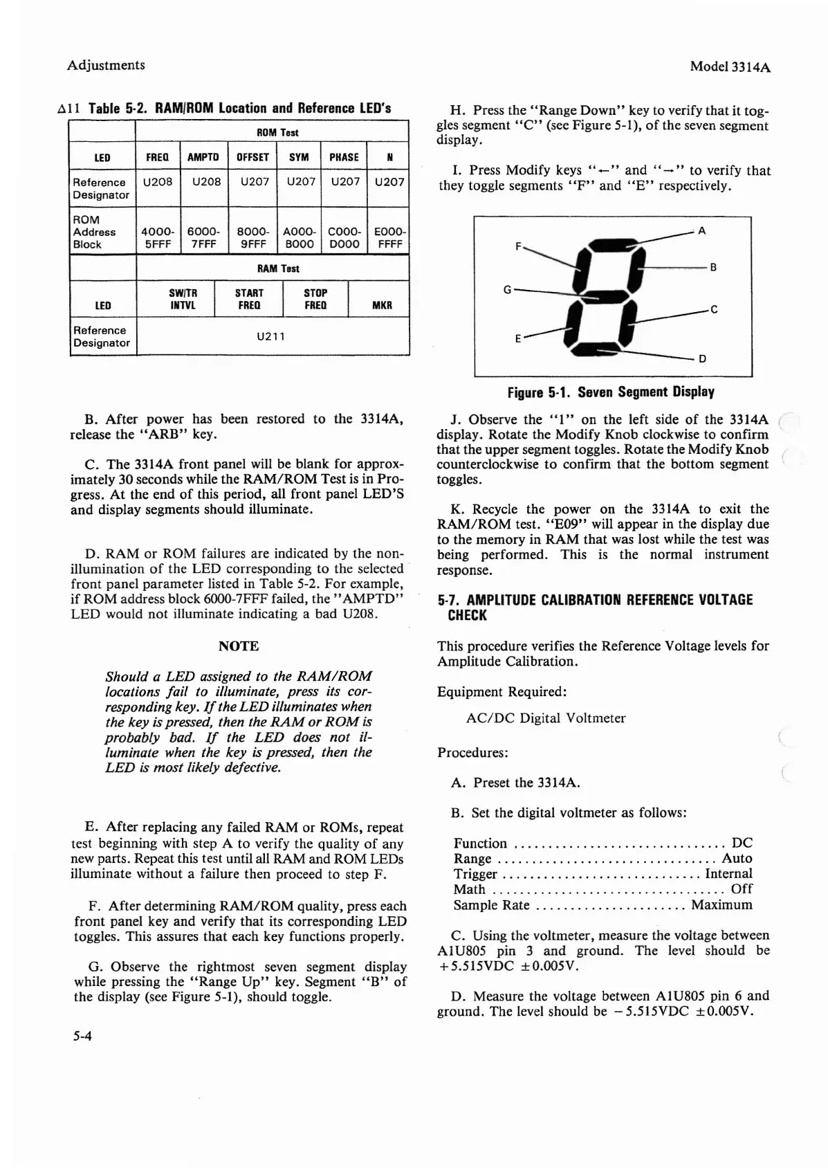
G. Observe the rightmost seven segment display
while pressing the
"Range
Up"
key. Segment
"B"
of
the display (see Figure 5-1), should toggle.
5-4
Model 3314A
H. Press the
"Range
Down"
key to verify
that
it
tog
-
gles segment •'C" (see Figure 5-1),
of
the seven segment
display.
I.
Press Modify keys ..
-"
and
..
-"
to verify
that
they toggle segments
"F"
and
"E"
respectively.
Figure
5-1.
Seven
Segment
Display
J. Observe
the
"I
" on the left side
of
the 3314A
display. Rotate the Modify Knob clockwise to
confirm
that
the upper segment toggles. Rotate the Modify
Knob
counterclockwise to confirm
that
the
bottom
segment
toggles.
K. Recycle the power on
the
3314A to exit
the
RAM/ROM
test.
"E09"
will
appear
in the display
due
to the memory in
RAM
that
was lost while the test was
being performed. This is
the
normal instrument
response.
5-7.
AMPLITUDE
CALIBRATION
REFERENCE
VOLTAGE
CHECK
This procedure verifies the Reference Voltage levels
for
Amplitude Calibration.
Equipment Required:
AC/DC
Digital Voltmeter
Procedures:
A. Preset the 3314A.
B. Set the digital voltmeter as follows:
Function DC
Range
Auto
Trigger . . . . . . . . . . . . . . . . . . . . . . . . . . . . . Internal
Math
_ _
Off
Sample Rate Maximum
C. Using the voltmeter, measure the voltage between
Al
U805 pin 3
and
ground
.
The
level should be
+5
.515VDC ± O.
OO
5V.
D. Measure the voltage between
Al
U805 pin 6
and
ground. The level should be - 5.5I5VDC ± O.005V.


 To Next Page
 Loading...