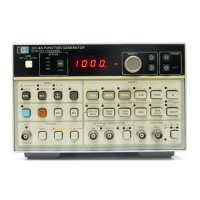
Model3314A
NOTE
If
the voltages measured in steps C and
Dare
outside their given tolerances, check the
levels
of
the
+15VDC
and
-15VDC
sup-
plies.
Adjust
the supplies
if
necessary
and
repeat steps C
and
D
of
this test.
If
the
voltages still do
not
meet the specification,
check the values
of
A1R804 through A1R807
against those given on the schematic.
AIU805
may
also need to be replaced.
5-8.
MULTIPLEX
DAC
OFFSET
ADJUSTMENT
This adjustment cancels the offset voltage
of
A2U207,
thus assuring the proper functioning of the Multiplex
DAC.
Equipment Required:
AC/DC
Digital Voltmeter
E\
:edures:
A. Preset the 3314A.
B. Set the digital voltmeter as follows:
Function DC
Range Auto
Trigger Internal
Math
Off
Sample Rate Maximum
NOTE
Due to the precision required
for
this adjust-
ment, connect the voltmeter ground directly
to
A2J8
pin 4
of
the 3314A.
C. Using the voltmeter, measure the DC voltage be-
t en A2U213 pin 1 and ground. The level should be
O.vVDC
±O.lmV.
D.
If
necessary, adjust A2R212 (DAC Offset) until
O.OVDC
±O.lmV
is measured.
NOTE
Sweep
and
Amplitude accuracy are affected
by this adjustment.
Adjustments
5·9.
FREQUENCY
ACCURACY
CALIBRATION
ADJUSTMENT
This adjustment sets the Frequency Calibration poten-
tiometer to the center
of
the calibration range, thus in-
suring the 3314A's ability to calibrate frequency over its
entire operating temperature range.
Equipment Required:
NONE
Procedures:
A. Preset the 3314A.
B. Set A3S1(4) and A3S1(5) to the
"closed"
posi-
tion.
C.
Turn
the 3314A OFF, then ON.
D. Return A3S1(4) and A3S1(5) to the
"open"
posi-
tion. (The 3314A is now in Test Mode 01.)
E. Adjust A2R429 (Freq Cal) until 000 ± 002 is
shown in the 3314A display.
F. Press the
"Range
Down"
key to return the 3314A
to normal operation. Verify that the instrument passes
the calibration without
"E31"
appearing in the
display".
*NOTE
If
"E31"
continues to be displayed, press
the
"Range
Up"
key
four
times to set the
frequency to 10MHz.
If
"E31 '.' was
displayed as the frequency changed to
lOMHz, adjust
AIC218
(10MHz
Adjust)
in
either direction and perform a calibration
("Blue",
"RCL
"). Repeat adjustment
and
calibration until
"E31"
no longer appears
when the calibration
is performed.
(If
E31
continued to appear afteradjusting A
1C218,
check the power supplies
for
proper
amplitude, adjust
if
necessary,
and
repeat
Frequency Accuracy Calibration adjust-
ment.)
5:10.
Z·AXIS
POLARITY
OBSERVATION
This procedure measures the amplitude
of
the Z-Axis
Marker pulse
and
verifies its change in polarity when the
Z-Axis switch is toggled.
5-5


 To Next Page