Adjustments
Model 3314A
Z-AX
151 3314
OSCILLOSOPE
L
I~
Lil
I
lotlEJ
~
\
0
[L
L l
Ll
(,. u
c..
u
c..
LLLLLL
"
[L L L
LI
u
....
(,. v "
LLLLLL
[""""II""""I~
~
~
~
@)
L L L
~ ~
L e
~~L
CH
A
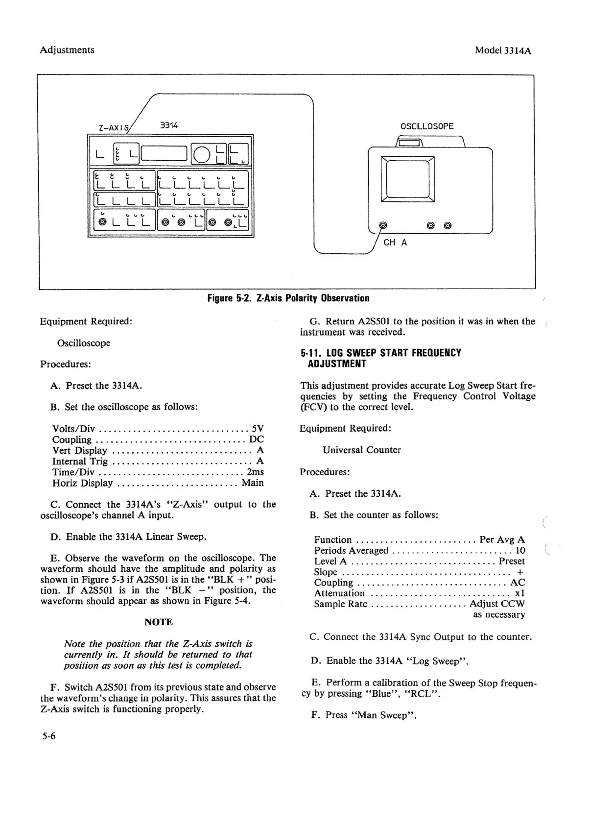
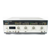
Figure
5·2.
Z·Axis
Polaritv
Observation
Equipment Required:
Oscilloscope
Procedures:
A. Preset the 3314A.
B. Set the oscilloscope as follows:
Volts/Div 5V
Coupling DC
Vert Display A
Internal Trig . . . . . . . . . . . . . . . . . . . . . . . . . . A
Time/Div 2ms
Horiz Display . . . . . . . . . . . . . . . . . . . .
..
Main
C. Connect the 3314A's
"Z
-Axis" output to the
oscilloscope's channel A input.
D. Enable the 3314A Linear Sweep.
E. Observe the waveform on the oscilloscope. The
waveform should have the amplitude and polarity as
shown in Figure 5-3 if A2S501 is in the
"BLK
+"
posi-
tion.
If
A2S501 is in the
"BLK
-"
position, the
waveform should appear as shown in Figure 5-4.
NOTE
Note the position that the Z-Axis switch is
currently in. It should be returned to that
position as soon as this test is completed.
F. Switch A2S501 from its previous state and observe
the waveform's change in polarity. This assures that the
Z-Axis switch is functioning properly.
5-6
G. Return A2S501 to the position it was in when the
instrument was received.
5·11.
LOG
SWEEP
START
FREOUENCY
ADJUSTMENT
This adjustment provides accurate Log Sweep Start fre-
quencies by setting the Frequency Control Voltage
(FCV) to the correct level.
Equipment Required:
Universal Counter
Procedures:
A. Preset the 3314A.
B. Set the counter as follows:
Function
Per
Avg A
Periods Averaged . . . . . . . . . . . . . . . . . . . . . . . . . 10
Level A Preset
Slope
+
Coupling AC
Attenuation xl
Sample Rate Adjust CCW
as necessary
C. Connect the 3314A Sync Output to the counter.
D. Enable the 3314A
"Log
Sweep".
E. Perform a calibration
of
the Sweep Stop frequen-
cy by pressing
"Blue",
"RCL"
.
F. Press
"Man
Sweep".


 To Next Page