EasyManua.ls Logo

HP 3314A - Page 82

HP 3314A
242 pages
Print Icon
To Next Page IconTo Next Page
To Previous Page IconTo Previous Page
Loading...
Model3314A
3314
L
[g
l I
[Q1J
EJ
IL
L L l l
LLLLLL
'"
IL L L L
ILLLLLL
1
"'
''' '''
'''
I[
....
....
I~
~L
L
L~
~
L~
~
OUT
Adjustments
AC/DC
DIG
ITAL
VOLTMETER
II
II
50
OHM
FEED
THRU
TERMINA
TION
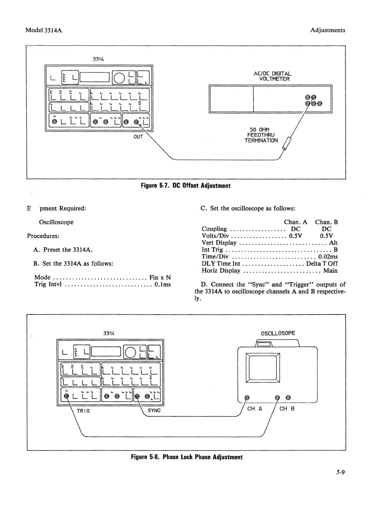
I;' pment Required:
Figure
5
-7.
DC
Offset
Adjustment
C. Set the oscilloscope as follows:
Oscilloscope
Procedures:
A. Preset the 3314A.
B. Set the 3314A as follows:
Mode Fin
x N
Tr
ig Intvl . . _ _ " 0.1ms
3314
L
[gl
I
[Q1JEJ
[L
1-
LL IL L L L L
!-
IL
L L L
ILLLLLL
1
~
"
~
"
LI
~:L
SYNC
Chan. A Chan. B
Coupling DC DC
Volts/Div 0.5V 0.5V
Vert Display " _. . . . . . . . . . . . . Alt
Int Trig
B
Time/ Div 0.02ms
DLY Time Int Delta T
Off
Horiz Display . . . . . . . . . . . . . . . . . . . . . Main
D. Connect the " Syn
c"
and
"Tr
igger" outputs
of
the 3314A to oscilloscope channels A and B respective-
ly.
OSC
ILLOSOPE
o
Figure
5·8.
Phase
Lock
Phase
Adjustment
5-9