Adjustments
Model 3314A
SYNC
SPECTRUM
ANALYZER
D
3314
ItL L
LILLLLL1-
IL L L
LILLLLLL
IGL L L
II
e
~
(')
~
tl
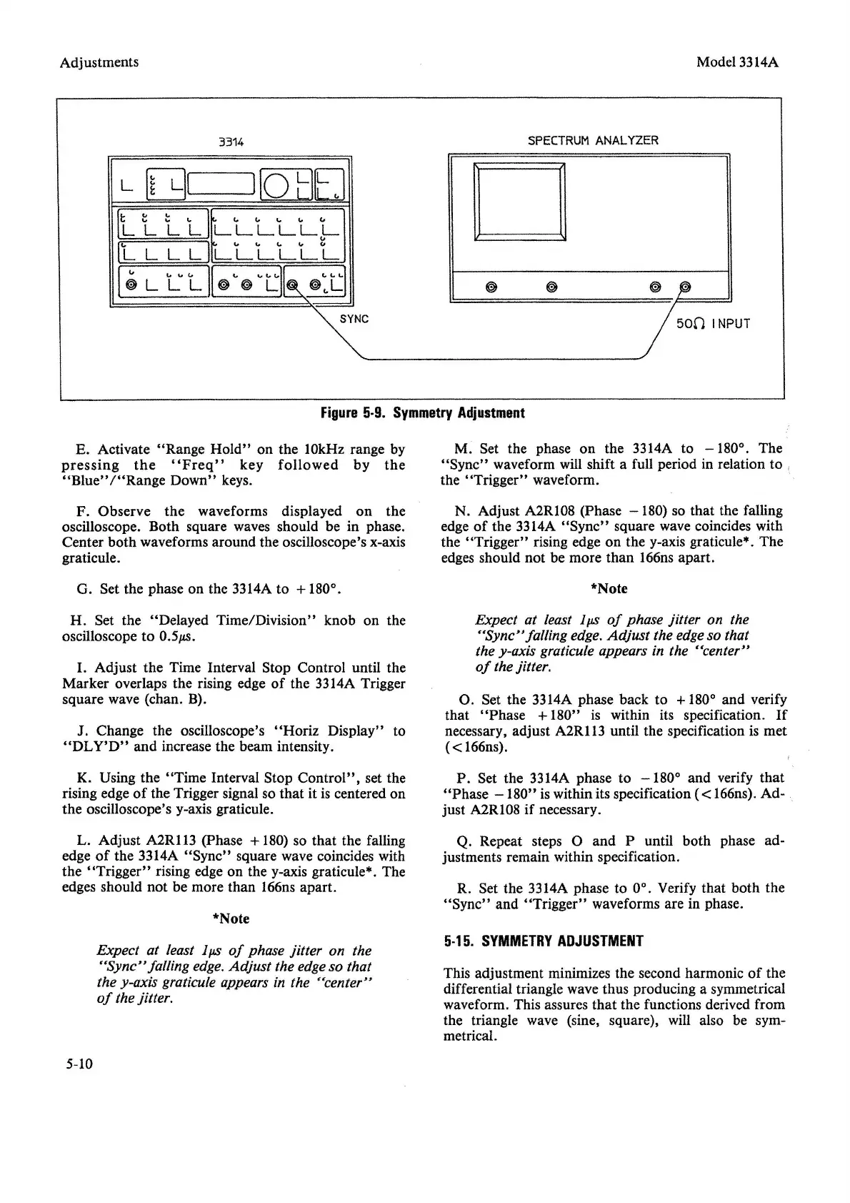
Figure
5·9.
Symmetry
Adjustment
E. Activate "Range
Hold"
on the 10kHz range by
pressing
the
"Freq"
key
followed
by
the
"Blue"
/"Range
Down"
keys.
M. Set the phase on the 3314A to
-180°.
The
"Sync"
waveform will shift a full period in relation to
the
"Trigger"
waveform.
F. Observe the waveforms displayed on the
oscilloscope. Both square waves should be in phase.
Center both waveforms around the oscilloscope's x-axis
graticule.
N. Adjust A2R108 (Phase
-180)
so that the falling
edge
of
the 3314A
"Sync"
square wave coincides with
the "Trigger" rising edge on the y-axis graticule". The
edges should not be more than 166ns apart.
G. Set the phase on the 3314A to
+180°.
*Note
H. Set the "Delayed Time/Division" knob on the
oscilloscope to
0.5p.s.
I. Adjust the Time Interval Stop Control until the
Marker overlaps the rising edge
of
the 3314A Trigger
square wave (chan. B).
J. Change the oscilloscope's
"Horiz
Display" to
"DLY'D"
and increase the beam intensity.
Expect at least Ips
of
phase jitter on the
"Sync"
falling edge.
Adjust
the edgeso that
the y-axis graticule appears in the "center"
of
the jitter.
O. Set the 3314A phase back to +180° and verify
that
"Phase
+180" is within its specification.
If
necessary, adjust A2R113 until the specification is met
« 166ns).
K. Using the
"Time
Interval Stop
Control",
set the
rising edge
of
the Trigger signal so that it is centered on
the oscilloscope's y-axis graticule.
P. Set the 3314A phase to
-180°
and verify
that
"Phase
-180"
is within its specification (<166ns).Ad-
just A2R108 if necessary.
L. Adjust A2RI13 (phase +180) so that the falling
edge
of
the 3314A
"Sync"
square wave coincides with
the
"Trigger"
rising edge on the y-axis graticule*. The
edges should not be more than 166ns apart.
*Note
Q. Repeat steps 0 and P until both phase ad-
justments remain within specification.
R. Set the 3314A phase to 0°. Verify that both the
"Sync"
and
"Trigger"
waveforms are in phase.
Expect at least Ips
of
phase jitter on the
"Sync"
falling edge. Adjust the edgeso that
the y-axis graticule appears in the "center"
of
the jitter.
5·15.
SYMMETRY
ADJUSTMENT
This adjustment minimizes the second harmonic
of
the
differential triangle wave thus producing a symmetrical
waveform. This assures that the functions derived from
the triangle wave (sine, square), will also be sym-
metrical.
5-10


 To Next Page