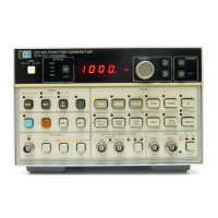
Model3314A
Equipment Required:
Spectrum Analyzer
Procedures:
A. Preset the 3314A.
B. Set the 3314A as follows:
Amplitude lOVp-p
Function square
C. Press
"Instr
Preset"
on the spectrum analyzer.
D. Set the spectrum analyzer as follows:
Stop Freq . . . . . . . . . . . . . . . . . . . . . . . . . . . . 10kHz
Counter On
Connect the 3314Ato the spectrum analyzer by first
removing phono cable
All1
from the instrument. Se-
c( , move the
"Sync"
cable from
All2
to
All
1 and
connect the 3314A to the analyzer's
50n input via the
3314's
"Sync"
output. (See Figure 5-9).
F. Press
"Manual"
on the spectrum analyzer
and
enter 1kHz. This places the spectrum analyzer marker
over the 3314A fundamental.
G. After the counter reading on the spectrum
analyzer screen has stabilized, press the following key
sequence:
"MKR-OFS-STEP"
"Counter"
(Off)
"Offset"
"Enter
Offset"
"Manual"
(Enter OHz)
"Manual"
"Up
Arrow"
Up
Arrow"
1· marker on the spectrum analyzer screen is now over
the second harmonic
of
the 1kHz triangle wave signal.
H. Note the amplitude
of
the second harmonic (see
screen upper right) . This level should be
$ - 75dB. If
necessary, adjust AIR110 (Symmetry) on the 3314A un-
til this level is brought into specification.
I.
Press
"Cont"
on the spectrum analyzer. Observe
that the 1kHz spectrum up to the 9th harmonic is
displayed on the screen.
J. Check the level
of
the EVEN harmonics (4th-8th)
to verify that they are
$
-75dB.
K. Place phono cable
AU8
back in the instrument
and
move the
"Sync"
cable back to Al.Il,
Adjustments
NOTE
If
this adjustment fails to yield satisfactory
results, check
for
possible problems with
either the Freq/Sym
DAC
or the
AIU103
biasing circuit.
5·16.
HOLD
PHASE
ZERO
ADJUSTMENT
This procedure sets the zero point
of
the servo loop by
adjusting the offset
of
the input to the Hold Phase Ser-
vo Amplifier.
Equipment Required:
Oscilloscope
Procedures:
A. Preset the 3314A.
B. Set the 3314A as follows:
Mode Gate
Frequency 10kHz
Amplitude lOVp-p
Function triangle
Trig Intvl " 1ms
C. Set the oscilloscope as follows:
Volts/Div 2V
Time/Div 0.2ms
Coupling
50n
Vert Display . . . . . . . . . . . . . . . . A
Int Trig A
Horiz Display Main
D. Connect the 3314A to the oscilloscope.
E. Using the Vertical Position knob on the
oscilloscope, adjust the display until the triangle wave is
centered around the x-axis graticule.
F
~
Observe the horizontal segment
of
the waveform
between the triangle bursts.
If
necessary, adjust AIR269
(Hold Phase Zero) until the segment is centered on the
x-axis graticule.
NOTE
Gate, N Cycle,
1/2
Cycle, and
ARB
modes
are affected by this adjustment.
5·17.
DC/AC
BALANCE
ADJUSTMENT
These adjustments minimize residual signals at
OV
amplitudes
and
insure amplitude accuracy while
"Amplitude Range
Hold"
is activated.
5-11


 To Next Page
 Loading...