Adjustments
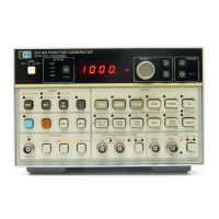
3314
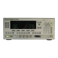
OSCILLOSCOPE
Model 3314A
LOI
110
tiE
IE'5\
\
0
Itl L
LI
c..
I" '"
c..
(,r
LLLLL!-
IL L L LI
....
c..
t. "" CI
LLLLLL
l~
~~~
\I
~
~~~I~
C~A
(l)
(l)
e L L
L(l)
(i)
L
(i)
..L
.,
J
~UT
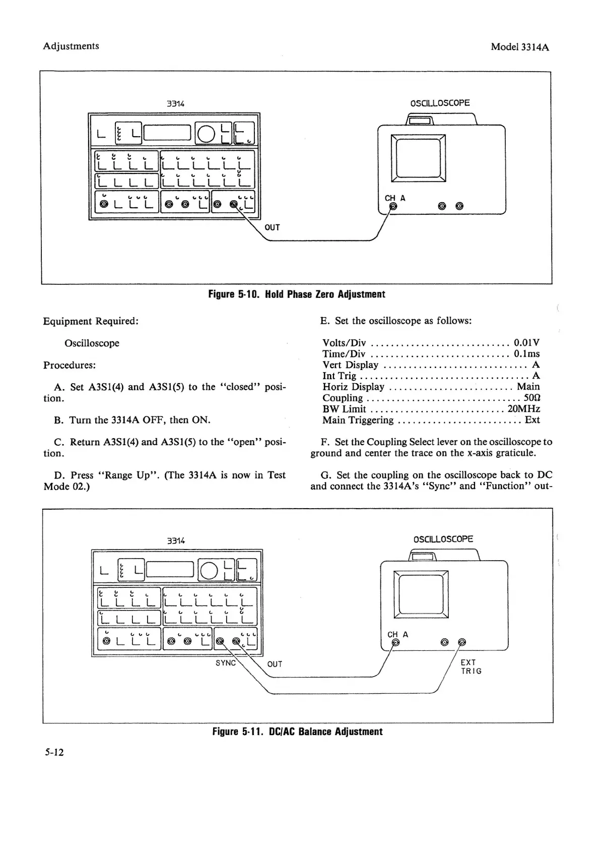
Figure
5·1
D.
Hold
Phase
Zero
Adjustment
Equipment Required:
Oscilloscope
Procedures:
A. Set A3S1(4)
and
A3S1(5) to the
"closed"
posi-
tion.
B. Turn the 3314A OFF, then ON.
C. Return A3S1(4) and A3S1(5) to the
"open"
posi-
tion.
D. Press
"Range
Up".
(The 3314A is now in Test
Mode 02.)
3314
E. Set the oscilloscope as follows:
Volts/Div
O.OIV
Time/Div
O.lms
Vert Display A
Int Trig A
Horiz Display . . . . . . . . . . . . . . . . . . . . . . .
..
Main
Coupling
50n
BW Limit 20MHz
Main Triggering
~
. Ext
F. Set the Coupling Select lever on the oscilloscope to
ground and center the trace on the x-axis graticule.
G. Set the coupling on the oscilloscope back to DC
and connect the 3314A's
"Sync"
and
"Function"
out-
OSCILLOSCOPE
L
01
I[Q]EJ
It l t
LILLLLLl-
IL L L L
ILLLLLL
I
~
L
LV
L
11
~
..
~
..
r]
OUT
o
CH
A
Figure
5·11.
DC/AC
Balance
Adjustment
5-12


 To Next Page