Model 3314A
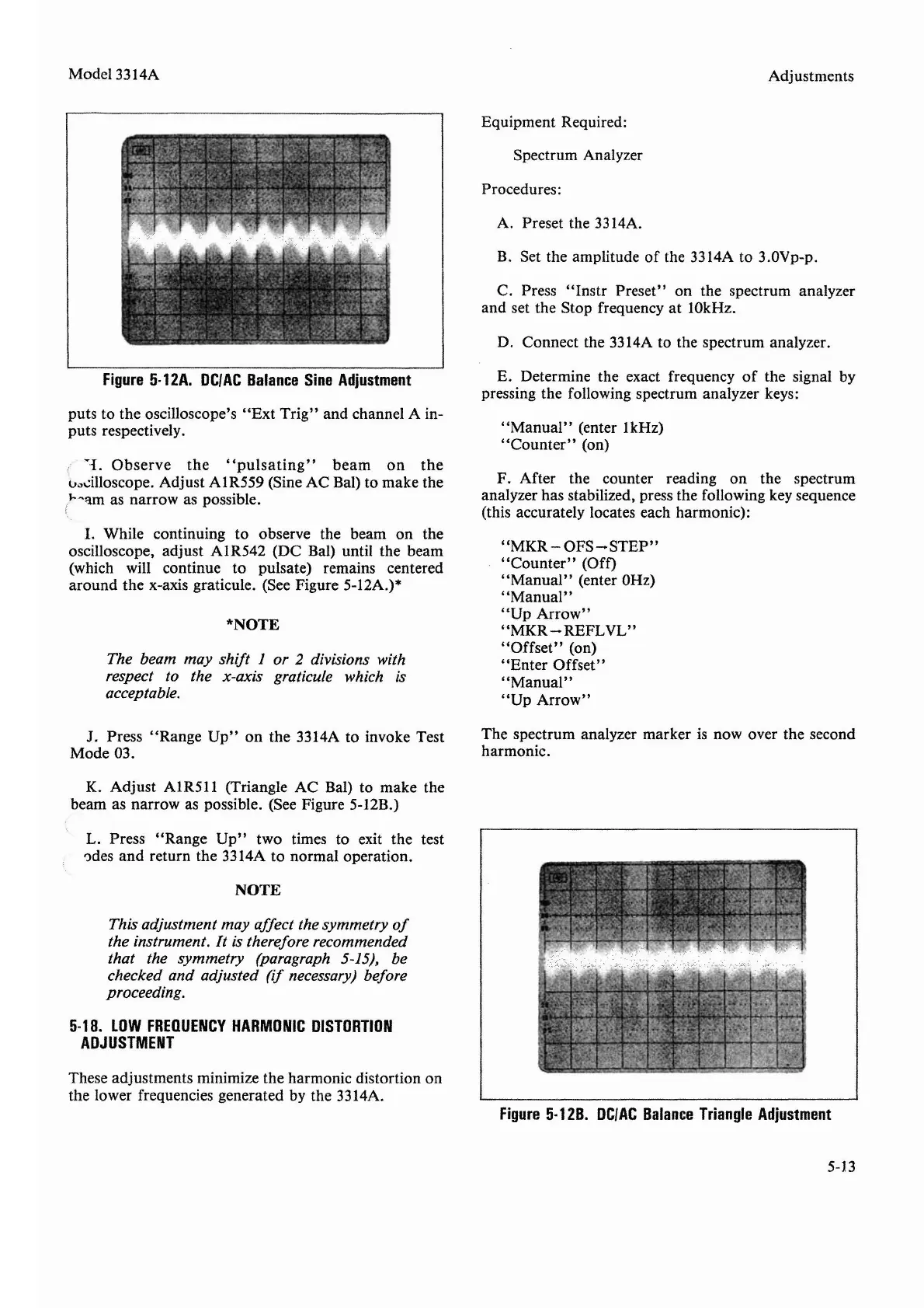
Figure
5-12A.
DCI
AC
Balance
Sine
Adjustment
puts to the oscilloscope's
"Ext
Trig"
and channel A in-
puts respectively.
~L
Observe
the
"pulsating"
beam
on
the
oscilloscope. Adjust AIR559 (Sine AC Bal) to make the
"~qm
as narrow as possible.
1. While continuing to observe the beam on the
oscilloscope, adjust AIR542 (DC Bal) until the beam
(which will continue to pulsate) remains centered
around the x-axis graticule. (See Figure 5-12A.)*
*NOTE
The beam may shift 1 or 2 divisions with
respect to the x-axis graticule which is
acceptable.
J. Press "Range
Up"
on the 3314A to invoke Test
Mode 03.
K. Adjust AIR511 (Triangle AC Bal) to make the
beam as narrow as possible. (See Figure 5-12B.)
L. Press "Range
Up"
two times to exit the test
odes
and
return the 3314A to normal operation.
NOTE
This adjustment may affect the symmetry
of
the instrument. It is therefore recommended
that the symmetry (paragraph 5-15), be
checked and adjusted
(if
necessary) before
proceeding.
5-18.
LOW
FREQUENCY
HARMONIC
DISTORTION
ADJUSTMENT
These adjustments minimize the harmonic distortion on
the lower frequencies generated by the 3314A.
Adjustments
Equipment Required:
Spectrum Analyzer
Procedures:
A. Preset the 3314A.
B. Set the amplitude
of
the 3314A to 3.0Vp-p.
C. Press
"Instr
Preset" on the spectrum analyzer
and
set the Stop frequency at 10kHz.
D. Connect the 3314A to the spectrum analyzer.
E. Determine the exact frequency
of
the signal by
pressing the following spectrum analyzer keys:
"Manual"
(enter 1kHz)
"Counter"
(on)
F. After the counter reading on the spectrum
analyzer has stabilized, press the following key sequence
(this accurately locates each harmonic):
"MKR
-
OFS-STEP"
"Counter"
(Off)
"Manual"
(enter OHz)
"Manual"
"Up
Arrow"
"MKR
- REFL
VL"
"Offset"
(on)
"Enter
Offset"
"Manual"
"Up
Arrow"
The spectrum analyzer marker is now over the second
harmonic.
Figure
5-12B.
DC/AC
Balance
Triangle
Adjustment
5-13


 To Next Page