Adjustments
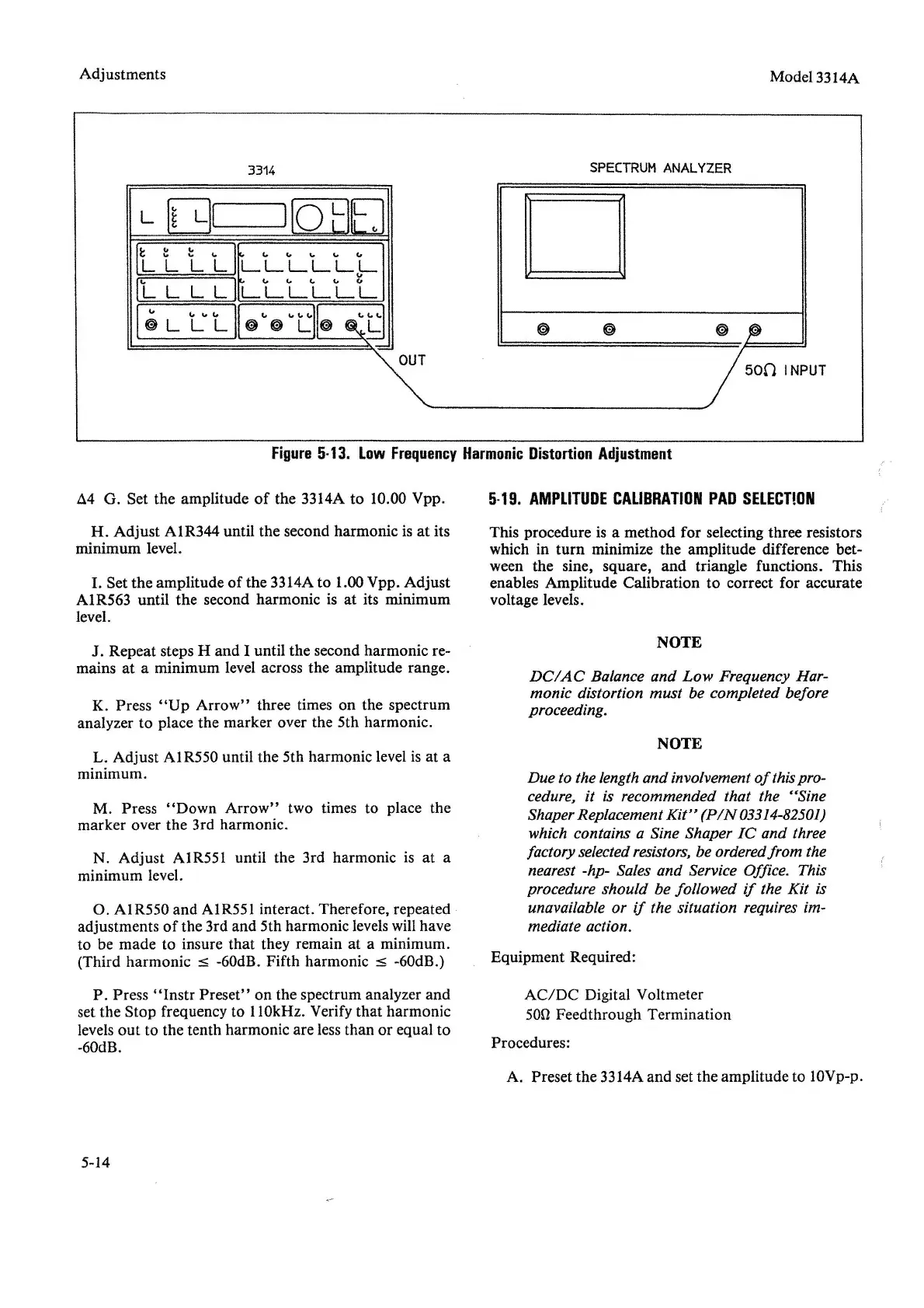
3314
OUT
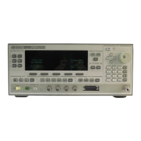
SPECTRUM
ANALYZER
D
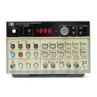
Model 3314A
Figure
5-13.
Low
Frequency
Harmonic
Distortion
Adjustment
.1.4
G. Set the amplitude
of
the 3314A to 10.00 Vpp.
H. Adjust AIR344 until the second harmonic is at its
minimum level.
I.
Set the amplitude
of
the 3314Ato 1.00 Vpp. Adjust
A1R563 until the second harmonic is at its minimum
level.
J. Repeat steps H and I until the second harmonic re-
mains at a minimum level across the amplitude range.
K. Press
"Up
Arrow"
three times on the spectrum
analyzer to place the marker over the 5th harmonic.
L. Adjust A1R550 until the 5th harmonic level is at a
minimum.
M. Press
"Down
Arrow"
two times to place the
marker over the 3rd harmonic.
N. Adjust AIR551 until the 3rd harmonic is at a
minimum level.
O. AIR550 and A1R551 interact. Therefore, repeated
adjustments
of
the 3rd and 5th harmonic levelswillhave
to be made to insure that they remain at a minimum.
(Third harmonic
s -60dB. Fifth harmonic s -60dB.)
P. Press
"Instr
Preset" on the spectrum analyzer and
set the Stop frequency to 110kHz. Verify that harmonic
levels
out
to the tenth harmonic are less than or equal to
-60dB.
5-14
5-19.
AMPLITUDE
CALIBRATION
PAD
SELECTION
This procedure is a method for selecting three resistors
which in turn minimize the amplitude difference bet-
ween the sine, square, and triangle functions. This
enables Amplitude Calibration to correct for accurate
voltage levels.
NOTE
DCIAC
Balance and
Low
Frequency Har-
monic distortion must be completed before
proceeding.
NOTE
Due to the lengthand involvement
of
thispro-
cedure, it is recommended that the
"Sine
Shaper Replacement
Kit"
(PIN
03314-82501)
which contains a Sine Shaper
IC
and three
factory selectedresistors, be orderedfrom the
nearest -hp- Sales and Service Office. This
procedure should be followed
if
the Kit is
unavailable or
if
the situation requires im-
mediate action.
Equipment Required:
AC/DC
Digital Voltmeter
50n Feedthrough Termination
Procedures:
A. Preset the 3314Aand set the amplitude to 10Vp-p.


 To Next Page