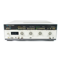
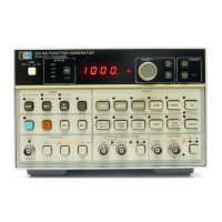
Model 3314A
3314
Adjustments
L
I~
LII
IIOclEJ
AC/DC D
IGITAL
VOLTMETER
IL
l LL I
L v
~
~ v
II
I
JiJ
LLLL
LL
"
.~~
IL
L L
LI
v
~
~ u
~
LLLLLL
I"
"""
II
"
"""l~
e L L L
~
(;)
L e
>...~
OU
T
50
OHM
FEEDTHRU
TERMINATION
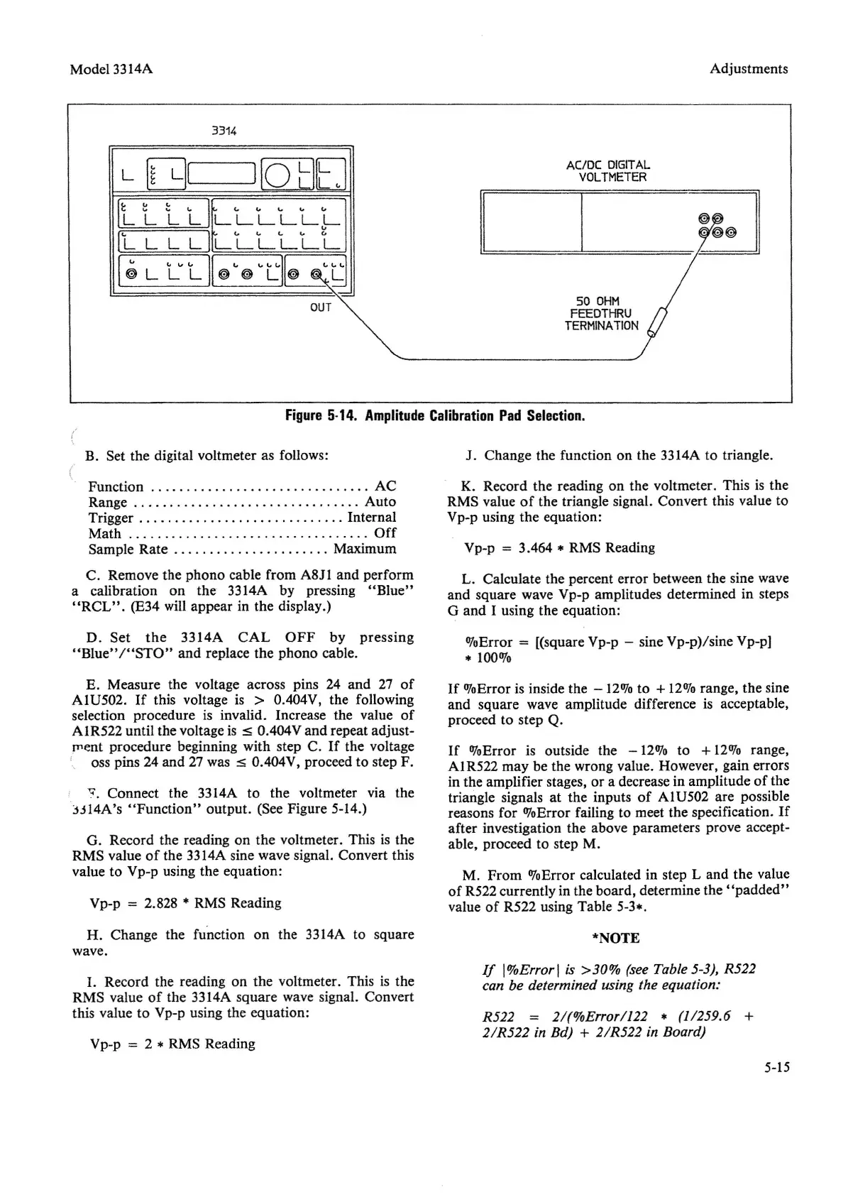
Figure
5-14.
Amplitude
Calibration
Pad
Selection.
B. Set
the
digital voltmeter as follows:
E. Measure the voltage across pins 24
and
27
of
AIU502.
If
this voltage is > 00404V, the following
selection procedure is invalid. Increase the value
of
AIR522
until the voltage is
:::5
00404V
and
repeat adjust-
ment procedure beginning with step C.
If
the voltage
i oss pins 24
and
27 was
:::5
O.404V, proceed to step F.
".
Connect
the
3314A to
the
voltmeter via the
j.:l14A's
"Function"
output.
(See Figure 5-14.)
G. Record the reading on
the
voltmeter.
Th
is is the
RMS value
of
the 3314A sine wave signal. Convert this
value to Vp-p using the equation:
Vp-p = 2.828 * RMS Reading
H. Change the function on the 3314A to square
wave.
I.
Record the reading on
the
voltmeter. This is the
RMS value
of
the 3314A square wave signal. Convert
this value to Vp-p using the
equat
ion :
Vp-p = 2 * RMS Reading
J. Change the function on the 3314A to triangle.
K. Record the reading on the voltmeter. This is the
RMS value
of
the triangle signal. Convert this value to
Vp-p using
the
equation:
Vp-p = 30464 * RMS Reading
L. Calculate the percent error between the sine wave
and
square wave Vp-p amplitudes determined in steps
G
and
I using the equation:
OJoError
= [(square Vp-p - sine Vp-p)/sine Vp-p]
* 100%
If
%Error
is inside the -12070 to +12% range, the sine
and
square wave amplitude difference is acceptable,
proceed to step Q.
If
%Error
is outside the
-12%
to + 12% range,
AIR522
may
be the wrong value. However, gain errors
in the amplifier stages, or a decrease in amplitude of the
triangle signals at
the
inputs
of
AIU502
are possible
reasons for
%Error
failing to meet the specification.
If
after investigation the above parameters prove accept-
able, proceed to step M.
M.
From
%Error
calculated in step L
and
the
value
of
R522 currently in the board, determine the
"padded"
value
of
R522 using Table 5-3*.
*NOTE
If
I%Errorl is
>30%
(see Table 5-3), R522
can be determined using the equation:
R522
= 2/(%Error/122 * (1/259.6 +
2/R522 in Bd) + 2/R522 in Board)
5-15


 To Next Page