Section VIII
THEORY
OF OPERATION
Model 3455A
8-54.
Squaring Amplifier.
The squaring amplifier
is
a
log
amplifier circuit
which takes the log of the input
voltage, or
in this
case since
there are two
transistors (Q9A and QUA)
in the
feedback loop,
takes twice the log
of the input
voltage. Therefore,
the output of the
squaring amplifier is
equal to 2 log
I V in I or log
1
V in I
*
.
8-55. Square Root and Averaging
Amplifier. The
square
root amplifier
reverses the action of
squaring amplifier.
The input to
the amplifier is
through logging
transistors
QllB
and Q9B. Output
of the square r
oot
ampli
fier is
equivalent
to
1/2
log
IV
in I*
or log
V
V In
I
^
.
The
operations of the square
root amplifier and the
averaging
amplifier are
simultaneous and
inter-dependent. The com-
bined
output of the two circuits is a dc
level proportional
to
the rms value of the input
signal.
B-S6.
AVERAGE
RESPONDING AC
CONVERTER
(Option 001).
8-57. General.
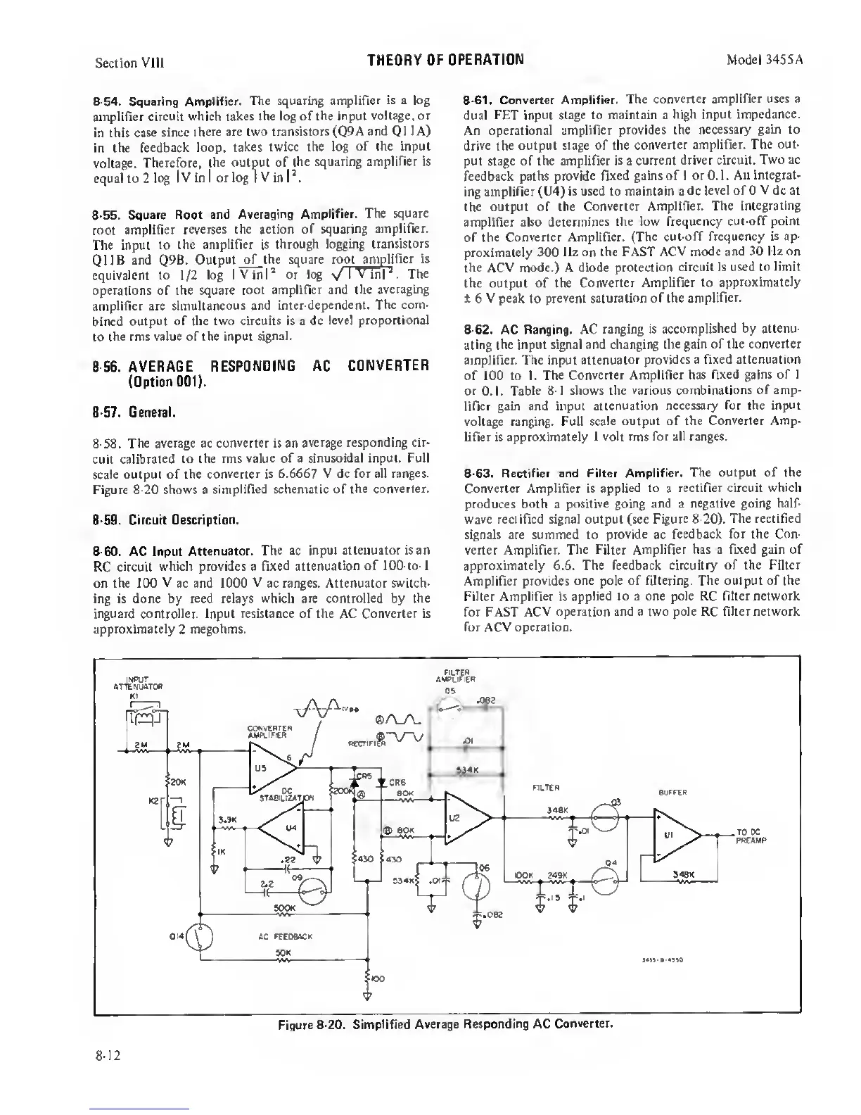
8-58.
The
average ac converter is an
average responding cir-
cuit calibrated
to the rms
value
of
a sinusoidal input. Full
scale
output of the
converter is 6.6667 V dc for all
ranges.
Figure
8-20
shows a
simplified schematic of
the converter.
8-59. Circuit Description.
8-60.
AC Input
Attenuator. The ac
input attenuator is an
RC circuit
which provides a fixed
attenuation of 100-to-l
on the 100 V ac and 1000
V
ac ranges. Attenuator switch-
ing is done by
reed
relays which are
controlled
by
the
inguard controller. Input resistance of the
AC
Converter is
approximately
2
megohms.
8-61. Converter
Amplifier. The
converter amplifier uses a
dual FET
input stage to maintain a
high input impedance.
An operational amplifier
provides the
necessary gain to
drive the output stage of the
converter amplifier. The
out-
put stage of the amplifier is a
current driver circuit.
Two
ac
feedback paths
provide fixed gains of 1 or 0.1. An
integrat-
ing
amplifier
(U4)
is used to maintain a
dc level of 0 V dc at
the
output of the
Converter Amplifier. The
integrating
amplifier also
determines the low
frequency cut-off point
of
the Converter Amplifier.
(The cut-off frequency is ap-
proximately
300 llz on the FAST ACV
mode and 30 Hz on
the
ACV mode.) A diode protection
circuit is used to limit
the output of the
Converter Amplifier to
approximately
±
6 V
peak
to
prevent saturation of the
amplifier.
8-62.
AC
Ranging.
AC
ranging is
accomplished
by
attenu-
ating
the input signal and changing the
gain of the converter
amplifier. The input
attenuator provides a fixed attenuation
of 100 to 1. The
Converter Amplifier has
fixed gains of
1
or 0.1.
Table
8-1
shows the
various combinations of amp-
lifier gain and input
attenuation necessary for the input
voltage ranging. Full
scale output of the
Converter Amp-
lifier is approximately
1 volt
rms
for all ranges.
8-63. Rectifier and Filter Amplifier.
The output of the
Converter Amplifier is applied to a
rectifier circuit which
produces both a
positive going and
a
negative going half-
wave rectified signal output (sec
Figure 8-20). The rectified
signals are summed to provide ac
feedback for the Con-
verter Amplifier.
The
Filter
Amplifier has a fixed gain of
approximately 6.6. The feedback circuitry of
the Filter
Amplifier
provides one pole of filtering. The output of the
Filter Amplifier is
applied to
a
one pole RC filter network
for FAST
ACV operation and
a
two pole RC filter network
for ACV operation.
Figure
8-20. Simplified Average
Responding
AC
Converter.
8-12
 Loading...


