Section
VUI Model 345SA
SERVICE GROUP
A
B-A-1.
TURN
ON CIRCUITRY
(IN6UAR0 AND OUTGUARD).
8'A-2. Turn-On failures will show up as an
inoperative
front panel and a blank display. Because of
the RAM's timing, the LED's
which
first light up
will vary with
instruments and also
on
the same
34SSA each time it is
powered
up. Therefore the
front panel will usually give
no
clues
to
the reason
for any turn-on
failures.
B-A-3.
Inguard/Qutguard Isolation.
8-A-4.
Assuming
that the
power supplies of the 34SSA are good, the Instrument Half Splitting
Technique (paragraph 8-176)
should
be the first
step in isolating turn-on failures. Either the inguard
or the outguard section could hang up the
343SA’$ turn-on sequence. The front panel indication does
not tell
where
the
fault is located. Therefore, the Half-Splitting Technique
should
be used to isolate
the fault
between
inguard or outguard section of the
345SA. If an extra 3455A and an In-
guard/Outguard
Service
Cable is not
available, the method described in Figure
8-45
may be used.
When
it is determined
which
section of the
3455A
is
at fault, go to the appropriate troubleshooting
section in
this service group (see paragraph
8-198
and Table
8-3).
B-A-5. Outguard Troubleshooting
(Schematic
B).
a. Check for a clock signal at A3TP5. If no
signal exists
or the
signal level is below 4
V(peak
to
peak), then troubleshoot the
outguard clock circuit.
b. Add A1C46 (part number
0160-3622) if the 3455A does not
have
one (schematic
8).
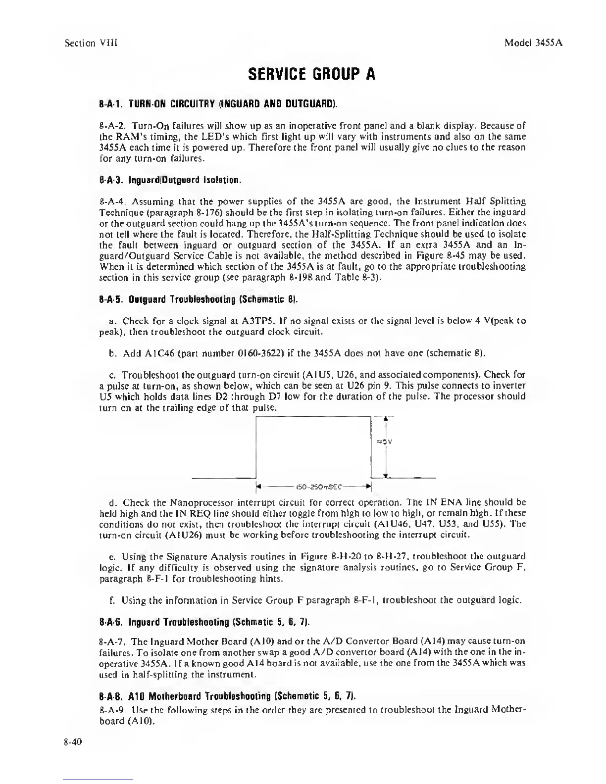
c. Troubleshoot the
outguard turn-on circuit (AIDS, U26, and associated components). Check for
a pulse at tum-on, as
shown below, which can be seen at U26 pin 9. This
pulse connects
to
inverter
U5
which holds data lines D2 through D7
low
for the duration
of
the
pulse. The processor should
turn on
at
the
trailing edge of that pulse.
I
1"
"SV
I Li
)•
-
—
60-250mSeC
*\
d.
Check
the
Nanoprocessor interrupt circuit for correct operation. The
IN ENA
line
should be
held
high
and the IN REQ line should either toggle from
high
to
low
to
high, or remain high. If these
conditions do not exist, then troubleshoot the
interrupt circuit (A1U46, U47, U53, and USS). The
turn-on circuit
(AIU26) must be
working
before troubleshooting the
interrupt circuit.
e.
Using the Signature Analysis routines in
Figure 8-H-20
to
8-H-27, troubleshoot the outguard
logic.
If any difficulty is
observed
using the
signature analysis routines, go to Service Group F,
paragraph 8-F-I for troubleshooting hints.
f. Using the information in
Service
Croup F
paragraph 8-F-l, troubleshoot the outguard logic.
B-A-6. Inguard Troubleshooting
ISchmatic
5, B, 7).
8-A-7.
The Inguard Mother
Board (AlO) and or the A/D
Convertor Board (A14) may cause turn-on
failures.
To isolate one from another
swap a good A/D
convertor
board (A14)
with the one in the in-
operative 345SA. If a
known
good A14
board is not
available,
use the
one from the 34S5A
which was
used in
half-splitting the instrument.
8 A-8. A10
Motherboard
Troubleshooting (Schematic
5,
B, 7).
8-A-9. Use the following steps in the
order
they
are presented to
troubleshoot the Inguard
Mother-
board (AlO).
8-40
 Loading...


