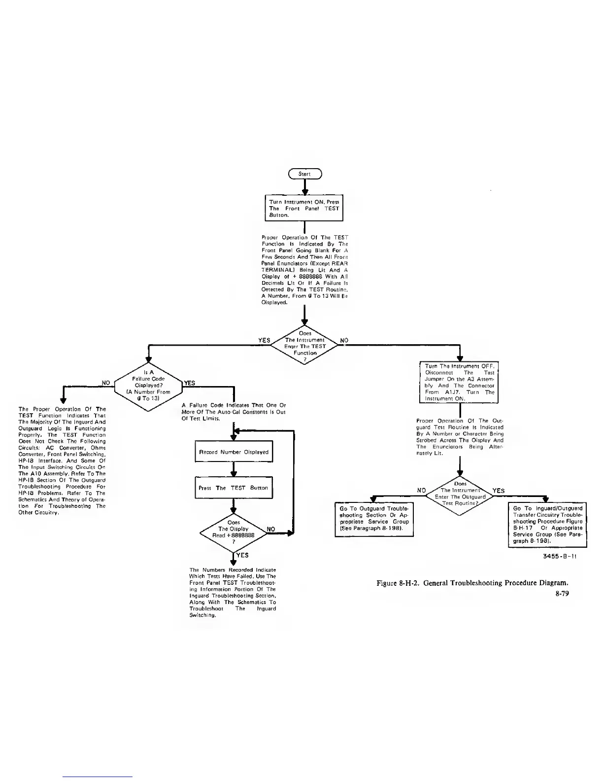
Turn Instrument
ON.
Press
The Front Panel TEST
Button.
Proper
Operation Of The
TEST
Function
Is
Indicated
Bv
The
Front Panel Going Blank For A
Few Secotvfs And Then All From
Panel Enunciators (Except REAi^
TERMINAL) Being Lit And
A
Display of
+
8888888 With A'l
Decimals Lit Or If
A
Failure
Is
Detected
By
The TEST Routine.
A
Number. From
0 To 1 3 Will Be
Displayed.
YES
The
Proper Operation Of
The
TEST Function Indicates That
The Majority Of The Inguard And
Outguard Logic Is Functioning
Properly. The TEST Function
Does Not Check The
Following
Circuits: AC Converter, Ohms
Converter, Front Panel Switching,
HP-IB Interface, And Some Of
The Input Switching Circuits On
The AID Assembly. Refer
To
The
HP-IB Section Of The Outguard
Troubleshooting Procedure For
HP-iB Problems. Refer
To
The
Schematics
And
Theory of Opera-
tion For Troubleshooting The
Other Circuitry.
YES
A
Failure
Code
Indicates That One
Or
More Of The
Auto-Cal Constants Is Out
Of Test
Limits.
Record Number Displayed
1
Turn The Instrument
OFF.
Disconnect The Test
Jumper On
the A3
Assem-
bly And The Connector
From
A1J7. Turn The
Instrument
ON,
Proper Operation Of The Out-
guard Test
Routine
Is
Indicated
By
A Number or Character Being
Strobed
Across
The
Display And
The Enurtciators Being Alter-
nately
Lit,
Go
To Outguard Trouble-
ahootlng Section Or
Ap-
propriate Service Group
(See
Paragraph 6-198).
The Numbers Recorded Indicate
Which Tests Have Failed.
Use
The
Front Panel TEST Troubleshoot-
ing Information Portion Of The
Inguard Troubleshooting Section,
Along With The Schematics To
Troubleshoot The Inguard
Switching.
Go
To Inguard/Outguard
Transfer Circuitry Trouble-
shooting Procedure Figure
8-H-17 Or Appropriate
Service Group (See
Para-
graph
8-1
98).
3455-B-ll
Figure 8-H-2.
General Troubleshooting Procedure Diagram.
8-79