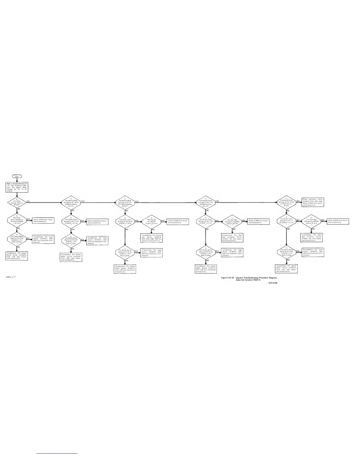
Start
With
A
Diaplav Reading Of
'’6"
(Test 6 Failure), Mea-
sure The Switch Drive
Voltage
On Pin
14 Of
A10U4.
is
N.
Is
'N.
^
The Switch Dri'
kJ A • Oir> 1 r
e^
4
>YES
The
Switch Drive
^N^YES
f”
L
A10U24 Appro iX
.
J
^
AlOUSApprcx.
^
^
Check
A10U4
And
Associ-
ated
Components.
Troubleshoot The Logic
Circuit (A10U13, U22,
U26 And Associated Com*
ponentsl.
Check A10U6 And Associ-
ated
Components.
Troubleshoot The Device !
Select Circuit
{A10UI3,
'
U14, U26 And Assooi-
'
ated Components).
|
1
Troubleshoot
The Device
Select Circuit
(A10U12,
U14, U26 And
Associ-
ated Components).
Troubleshoot The
Logic
Device Select^s,,^
Troubleshoot
The
Logic
^un'The
0
Sl!lec^S,. Troubleshoot
The
Logic
Circuit
(A10U16, U22,
1
Signal At
Pin
9 Of
Circuit (A10U16, U22,
^^Sional
n
9
Of |YES Circuit (A10U16, U22,
U26
And
Associated Com- L A10U16
>4
V J
U26
And Associated Com-
L
AlOl -4V J
*
U26
And Associaiied Com-
ponenis). -To •Peak^^^.x'''*^
poncnts),
\s^eal
’eok/'^ ponents).
NO
Troubleshoot The
Device
Select Circuit
(A10U16,
U14, U26 And Associated
Components).
Troubleshoot The
Device
Select Circuit IA10U16,
U14, U26
And Associated
Components).
Troubleshoot The
Device
Select Circuit (A10U16,
U14, U26
And Associ-
ated Components).
3455-D-7
Figure 8-H-lO. Inguard Troubleshooting Procedure Diagram,
Aulo-Cal Circuitry TEST 6.
8
-
97/
8-98