Volt/Div.
2a
ov
Wi'«foTm 1
4
,
*»**••
Titne/Div.
5
msec
^
S^t
^
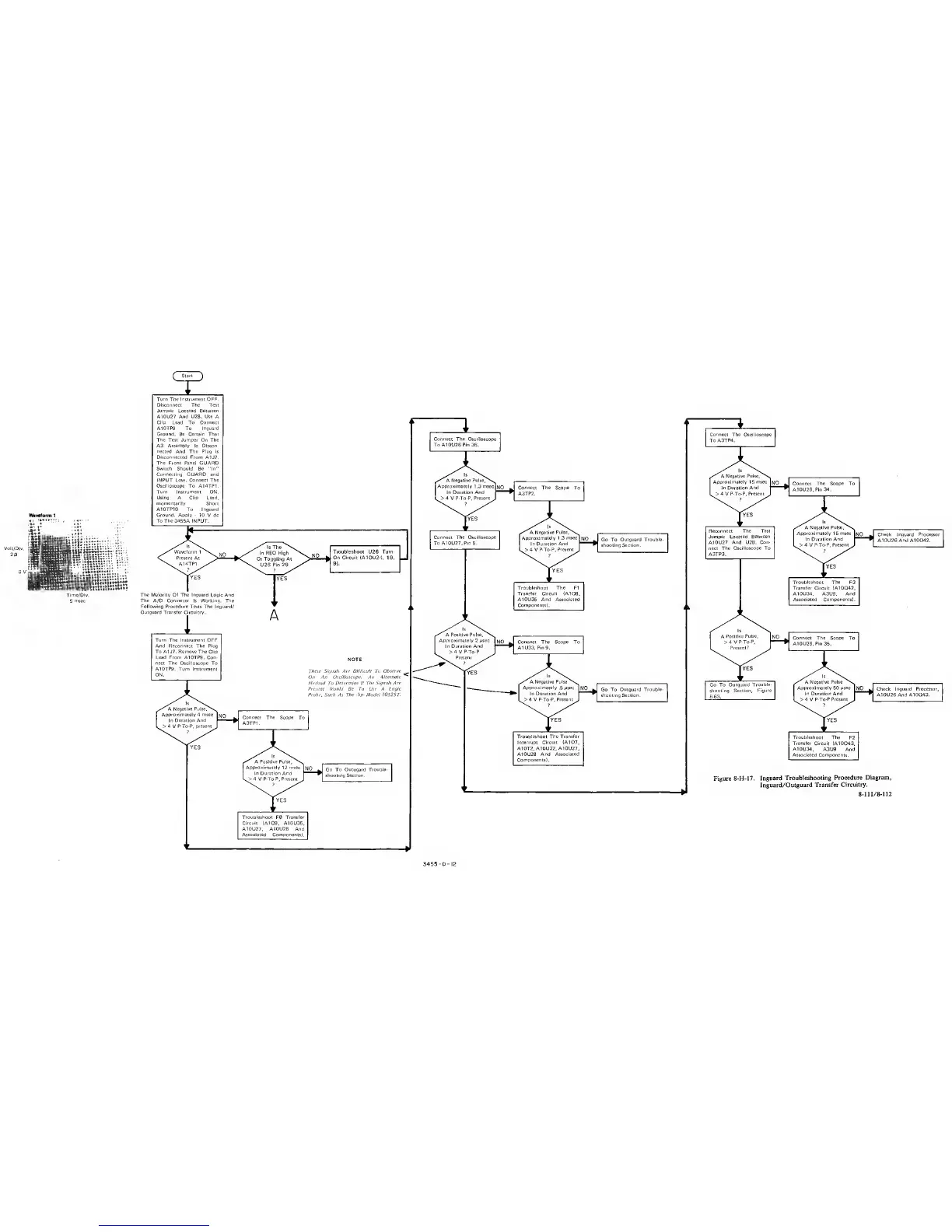
Turn The
Instrument
OPF.
Disconnect The Test
Jumper
Located Between
A10U27
And U28. Use
A
Clip Lead To Connect
A10TP9
To
Inguard
Ground. Be Certain That
The Test Jumper On The
A3
Assembly
Is
Discon-
nected And The Plug
Is
Disconnected From
A1J7.
The Front Panel
GUARD
Switch Should Be "In"
Connecting GUARD and
INPUT Low. Connect The
Oscilloscope
To A14TP1.
Turn Instrument
ON.
Using A Clio Lead,
momentarily
Short
A10TP10 To
Inguard
Ground. Apply
-
10 V dc
To
The
3455A INPUT.
The
Majority Of The Inguard Logic And
The
A/D
Converter
Is
Working.
The
Following Procedure Tests The Inguard/
Outguard Transfer Circuitry.
Troubleshoot U26 Turn-
On Circuit
(A10U24, 19.
9).
NOTE
Thne Signah Are Difficult Tv
Observe
On An Oscilloscope. An
Alternate
Method To
Determine II The Signals Are
1‘reseni Would Be
To
Use
A
Logic
Probe. Such As The -lip- Model I0S25T
Approximately
12
msec
NO
.
Go To Outugard Trouole-
In Duration
And
4
V
P-To-P. Present
.
shooting Section.
Troubleshoot
F0
Transfer
Circuit
(A1Q9, A10U35.
A10U27,
AI0U28 And
Associated Components)
.
»
Connect
The Oscilloscope
To
A3TP4.
1
Connect The Oscilloscope
To A10U26
Pin
36.
1 1
Troubleshoot The Transfer
Interrupt Circuit (A1Q7.
A10T2. A10U32, A10U27,
A10U28
And Associated
Components).
Troubleshoot The
F2
Transfer
Circuit
(A10Q43.
A10U34, A3U9 And
Associated Components.
Figure
8-H-17. Inguard
Troubleshooting Procedure
Diagram,
Inguard/Outguard Transfer
Circuitry.
8
-
111 /
8-112
3455-D-IZ