Section
IV Model
3455A
Tible
4-1
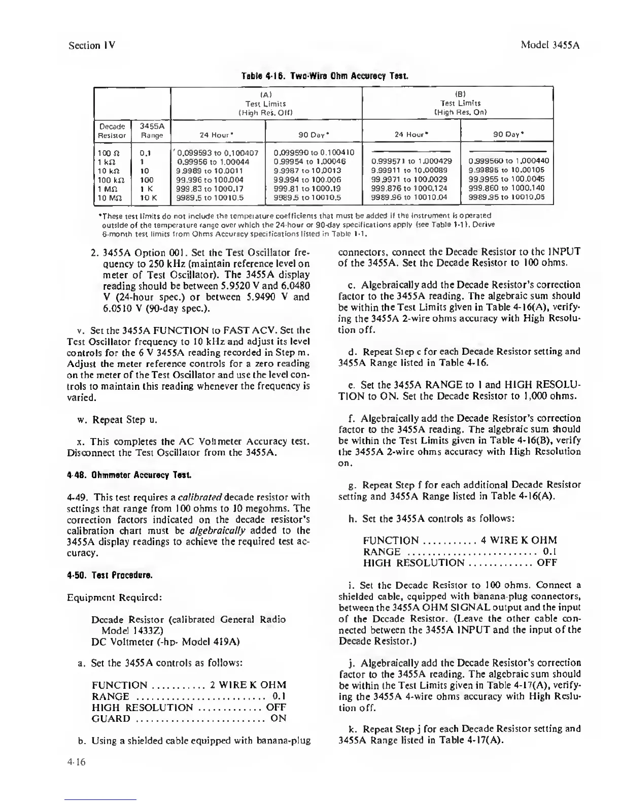
B. Two-Wire Ohm Acciraey Twt
(A)
Test Umit!
(High
Res.
0(f)
(8)
Test
Limits
(High Res. On)
OeMde
Resiitor
345SA
Range 24 Hour
•
90 Day*
24 Hour* 90 Day*
loon
t kn
0.1
1
'0.099593
to 0.100407
0.99956
to
1.00044
0.099590 toO.100410
099954
to
1.00046 0.999571 to
1.000429 0.999560 to 1
.000440
10 kn 10 9.9989 to
10.0011 9.9987 to 100013
9.99911
to
1000089 9.99895 to
10.00106
100 kn
100 99.996 to
100.004 99.994
to
100.006 999971 to 100.0029 99.9955
to 100.0045
1 Mn 1 K 999.8310
1000.17 999.81 to 1000.19 999.876 to
1000.124 999.860 to
1000.140
10 Mn 10 K 9989.5 to 10010.5
9989.510 10010.5 998996 to
1001004 9989.9510 10010.06
*Thete teti licniti
do
not include the tempefeture
coefficient! that mutt be added if the
intirumeni
ii operated
outilda of the
temperature ran9e
over
which the 24-hour or
90-day
specif teat
ioni
apply
(tee Table 1-1). Derive
6-mortth test limits from Ohmi Accuracy tpeciflcationt
listed
in
Table
t-1.
2. 345SA Option 001. Set the Test
Oscillator
fre-
quency to 2S0
kHz (maintain reference level on
meter of Test
Oscillator). The 3455A display
reading
should be between 5.9S20
V
and 6.IM80
V (24-hour spec.) or
between 5.9490 V
and
6.0510 V (90-day
spec.).
V. Set the 3455A FUNCTION to
FAST ACV. Set the
Test Oscillator frequency to
10
kHz
and adjust its
level
controls for the 6
V 3455A reading recorded in Step m.
Adjust the meter reference controls for a
zero reading
on the meter of the Test Oscillator
and
use
the level con-
trols to maintain this reading
whenever the frequency is
varied.
w. Repeat Step u.
X. This completes the
AC Voltmeter Accuracy test.
Disconnect
the
Test
Oscillator from the 3455A.
4-48.
Ohmmeter Accuracy Tnt
4-49. This
test
requires a calibrated decade resistor
with
settings that range from 100 ohms to 10
megohms.
The
correction factors indicated on
the decade resistor’s
calibration chart must
be
algebraically added to the
3455A display readings to
achieve
the
required
test ac-
curacy.
4-50.
Tut
Procedure.
Equipment
Required:
Decade
Resistor (calibrated General Radio
Model I433Z)
DC
Voltmeter
(-hp-
Model 4I9A)
a. Set
the 3455A controls as
follows:
FUNCTION
2 WIRE K OHM
RANGE
0.1
HIGH RESOLUTION
OFF
GUARD ON
b. Using a
shielded
cable
equipped with banana-plug
connectors,
connect the Decade Resistor to the
INPUT
of the 3455A. Set the Decade
Resistor to 100 ohms.
c.
Algebraically add the Decade Resistor’s
correction
factor to
the 3455A reading. The
algebraic
sum
should
be
within the Test Limits
given
in Table 4-16(A),
verify-
ing the
3455A 2-wire ohms accuracy
with High Resolu-
tion off.
d.
Repeat Step
c
for each Decade
Resistor setting and
3455A Range listed in
Table
4-16.
e. Set the
3455A RANGE to I and HIGH RESOLU-
TION to ON. Set
the Decade Resistor to
1
,000 ohms.
f.
Algebraically add the Decade Resistor’s
correction
factor to the 34SSA reading.
The algebraic sum should
be
within
the Test
Limits given in Table 4-16(B),
verify
the 3455A
2-wire
ohms
accuracy with High Resolution
on.
g.
Repeat Step f for each additional
Decade Resistor
setting and 3455A Range listed in
Table 4-16(A).
h. Set the 3455A controls as
follows:
FUNCTION
4 WIRE
K
OHM
RANGE
O.l
HIGH RESOLUTION
OFF
i. Set the Decade
Resistor to 100 ohms. Connect a
shielded cable,
equipped with banana-plug connectors,
between
the
3455A OHM SIGNAL output and the input
of the Decade
Resistor.
(Leave
the other cable
con-
nected
between the 3455A INPUT and
the input of the
Decade Resistor.)
j.
Algebraically add the Decade
Resistor’s correction
factor to
the 3455A reading. The algebraic sum
should
be
within the Test Limits
given
in Table
4-1
7(A),
verify-
ing the
3455A
4-wire
ohms accuracy
with High Reslu-
tion off.
k. Repeat Step
j
for
each E)ecade Resistor setting and
3455A
Range listed in Table 4-17(A).
4-16
 Loading...


