Model
3455A
Section
IV
TibU
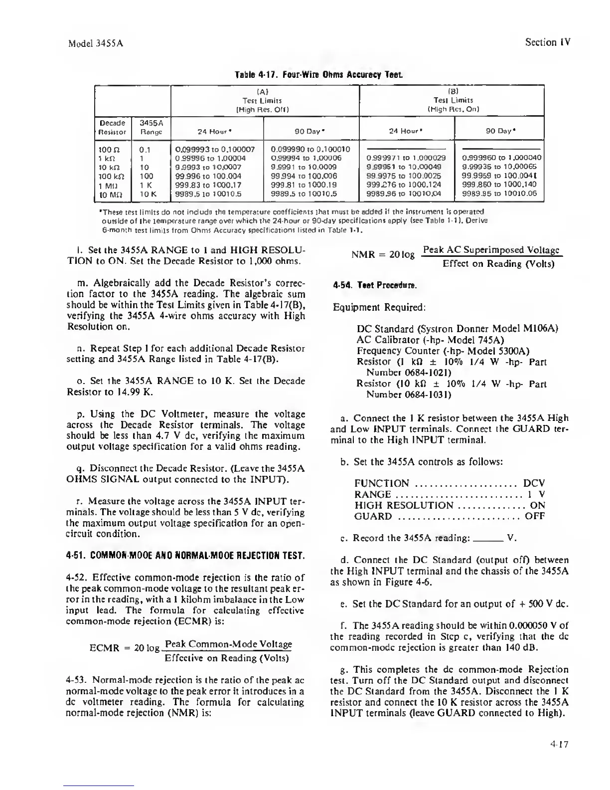
4-17.
Four-Wire Ohms Aecurocy Tost
(A)
Tew Limiti
(High Res. OH)
(B1
Test Limits
(High Res. On)
Decad6
Resiltor
3465A
Rangs 24
Hour
•
90
Day* 24
Hour*
90 Day*
100 n
1 kn
0.1
1
0.099993 to 0,100007
099996 to
1.00004
0.099990 to
0.100010
099994 to 1.00006
0999971
to
1.000029
0.999960
to 1 .000040
10 kn to
99993
to
10.0007 99991 TO 10.0009
999951
to
10.00049 9.99935 to 10.00065
100
kn 100 99 .996 to
100.004 99.994 to 100.006 99.9975 to 100.0025 99.9959
to 100.0041
1 Mil
1 K 999.83 to
1000.17 99991 to 1000.19 999.076 to
1000.124 999860 to 1000.140
10
MO
10 K
9989 5
to 10010.5 9989.5 to
10010.5 9989.96 to 10010.04 9989.95 to 10010.05
*Th»s« teti limits
do
not include the tempereture coefficients
that
must be added
if the instrument
is
operated
outside of the tempereture
rertge
over which the 24-hour or 90-dav
specifications apply (tee Table
1-1
).
Derive
6-monih
test limits from Ohms Accuracy
specifications listed in Table
1-1.
l. Set the 34S5A RANGE to I and HIGH RESOLU-
TION
to
ON.
Set the Decade Resistor to 1,000 ohms.
m. Algebraically add the Decade Resistor’s
correc-
tion factor to the 3455A reading. The algebraic
sum
should be
within
the Test Limits given in Table
4-17(B),
verifying
the 345SA
4-wire
ohms accuracy with High
Resolution
on.
n. Repeat Step I for each additional Decade Resistor
setting and 3455A Range listed
in
Table
4-17(B).
o. Set the 345SA RANGE
to
10 K. Set the Decade
Resistor to 14.99 K.
p.
Using the DC
Voltmeter,
measure the voltage
across
the Decade
Resistor
terminals. The
voltage
should be less than 4.7 V dc, verifying the maximum
output
voltage
specification for a valid ohms reading.
q.
Disconnect the
Decade Resistor.
(Leave
the 3455A
OHMS SIGNAL output connected
to the INPUT).
r. Measure
the
voltage across
the 3455A INPUT ter-
minals. The voltage should be less than
S
V dc, verifying
the
maximum
output
voltage
specification for an open-
circuit condition.
4-51.
COMMON MODE
AND
NORMAL MODE
REJECTION TEST.
4-52. Effective
common-mode rejection is the ratio of
the peak common-mode voltage
to the resultant peak er-
ror in the reading, with a I
kilohm
imbalance
in the
Low
input lead. The formula for calculating effective
common-mode rejection (ECMR) is:
ECMR
® ?n lAg
Common-Mode Voltage
Effective
on Reading (Volts)
4-53. Normal-mode
rejection is the ratio of the peak ac
normal-mode voltage
to the peak error it introduces in a
dc voltmeter reading. The
formula for calculating
normal-mode rejection (NMR) is:
NMR
=
20 log
Superimposed Voltage
Effect on Reading (Volts)
4-54.
Tut Pruadurt.
Equipment Required:
DC
Standard
(Systron Donner
Model M106A)
AC Calibrator
(-hp-
Model
745A)
Frequency Counter (-hp-
Model 5300A)
Resistor
(I kfl ± 10% 1/4 W -hp- Part
Number 0684-1021)
Resistor
(10 kft ± 10% 1/4 W -hp-
Part
Number 0684-1031)
a. Connect the 1 K
resistor between
the
34S5A High
and
Low INPUT terminals. Connect the GUARD ter-
minal to (he High INPUT terminal.
b. Set the 345SA controls as
follows:
FUNCTION DCV
RANGE 1 V
HIGH RESOLUTION ON
GUARD
OFF
c.
Record the 3455A reading:
V.
d. Connect the DC Standard (output off)
between
the High INPUT terminal and the chassis of the 345SA
as shown in Figure
4-6.
e. Set the DC Standard for an output of + 500
V
dc.
f. The 345SA reading should be
within
0.00(X}50 V of
the reading recorded in Step c,
verifying
that
the
dc
common-mode rejection is greater than
140
dB.
g.
This completes the dc common-mode Rejection
test. Turn off the DC Standard output
and disconnect
the DC
Standard from the 3455A. Disconnect the 1 K
resistor and connect the 10 K resistor across the 345SA
INPUT
terminals (leave GUARD connected to High).
4-17
 Loading...


