Model
3455A
Section IV
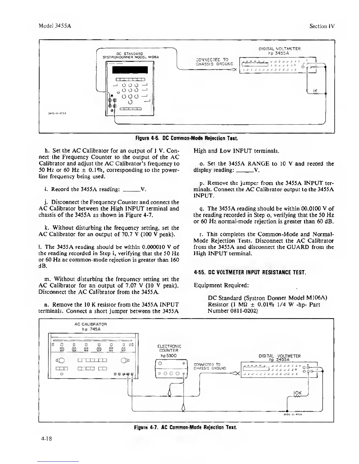
Figare
4-6.
DC Common-Mode Rojoctioo
Toot
h. Set (he AC Calibrator
for
an
output of I
V.
Con- High and
Low
INPUT terminals,
nect the Frequency Counter to the output of the AC
Calibrator and adjust the AC Calibrator’s frequency
to o. Set
the 3455A RANGE
to 10
V
and record the
50 Hz or 60 Hz ± O.IV#, corresponding to the power- display reading: V.
line
frequency being used.
p.
Remove the jumper
from the 3455A
INPUT
ter-
i.
Record the
34S5A reading:
V.
minals. Connect the AC Calibrator output to the 34S5A
INPUT.
j.
Disconnect the Frequency Counter and
connect the
AC
Calibrator
between
the High INPUT terminal and
q.
The 34S5A reading should be within 00.0100 V
of
chassis of the 3455A
as
shown
in Figure
4-7.
the reading recorded in Step o,
verifying
that the 50 Hz
or 60 Hz normal-mode
rejection is greater than 60 dB.
k. Without disturbing
the
frequency
setting, set the
AC Calibrator for an output
of
70.7 V
(100
V
peak). r.
This completes the
Common-Mode and Normal-
Mode Rejection
Tests.
Disconnect
the AC Calibrator
1.
The
3455A reading should be within 0.000010 V of from the 3455A and disconnect the GUARD from the
the reading recorded in Step
i,
verifying
that the 50 Hz
High
INPUT terminal,
or 60 Hz ac common-mode rejection
is
greater
than 160
dB.
4^55. DC VOLTMETER
INPUT RESISTANCE TEST.
m.
Without
disturbing the frequency setting set the
AC
Calibrator
for an output of 7.07
V
(10
V
peak).
Equipment Required:
Disconnect
the AC Calibrator from the 3455A.
DC Standard
(Systron
Donner Model
M106A)
n.
Remove
the 10 K resistor from the 3455A INPUT
Resistor
(1
MO
±
0.01 1/4 W
-hp- Part
terminals.
Connect a short jumper
between
the 3455A
Number
0811-0202)