Model 3455A Section V
SECTION V
ADJUSTMENTS
S-1.
INTRODUCTION.
S-2.
This section contains complete adjustment procedures
for the
Model
34S5A Digital
Voltmeter.
After the instru-
ment is
adjusted
according to the
procedures given
in this
section,
it
should meet the 24-hour accuracy specifications
listed in Table
1-1.
5-
3. EQUIPMENT REQUIRED.
S4. The test equipment required for the adjustments is
listed
at
the
beginning of each
adjustment
procedure and
in the
Recommended Test Equipment table in Section I.
If the recommended
equipment is
not
available, use sub-
stitute equipment that meets the critical specifications
given in the table.
6-
5. ADJUSTMENT INTERVAL.
5-6.
The 3455A adjustments should be
performed
at
90-
day or 6-month
intervals depending on the environmental
conditions
and
your specific accuracy requirements. Adjust-
ments should also be performed after the instrument
has
been repeaired.
5-7.
ADJUSTMENT SEQUENCE.
5-8.
The
3455A Adjustments must be performed
in
the
sequence in which they are presented. If the dc and ohms
accuracy of the instrument are satisfactory, the DC Zero
Adjustments and Reference Adjustments can be omitted
and the
RMS
or
Average Converter adjustments
can be
performed
to
optimize the ac voltmeter accuracy.
5-9.
TEST
POINT AND ADJUSTMENT LOCATIONS.
S-10. Test points and adjustments arc labeled on the top
inner cover and rear panel
(Reference
Module) of the
instrument or arc shown in figures designated in the adjust-
ment procedures.
S-11.
DC ZERO ADJUSTMENTS.
Equipment Required:
DC Digital Voltmeter
(-hp-
Model
3490A or 3455A)
a.
Remove
the 34SSA top outer cover and top inner
cover
to gain access to the AlO (Mother) board.
b.
Set the 34SSA controls as follows:
FUNCTION DCV
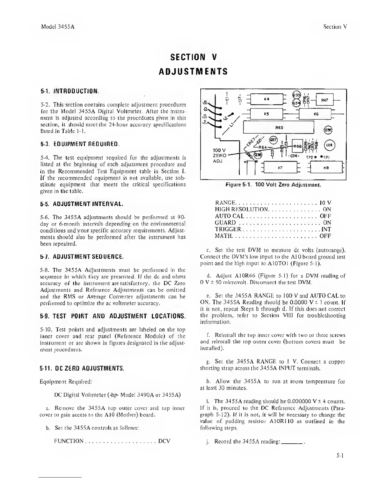
Figure 5-1. 100 Volt
Zero Adjustment.
RANGE
10
V
HIGH RESOLUTION ON
AUTO CAL OFF
GUARD
ON
TRIGGER INT
MATH OFF
c.
Set
the
test DVM
to measure dc
volts
(autorange).
Connect the DVM’s low input to the
A1 0 board ground test
point and the high input to AlOTOI
(Figure
5-1).
d. Adjust A10R66 (Figure 5-1) for
a
DVM reading
of
0 V ±
50
microvolt. Disconnect
the test
DVM.
e.
Set the
3455A
RANGE
to
lOOVand AUTOCALto
ON. The 3455A Reading should
be
0.0000 V ±
1
count.
If
it is not, repeat Steps b through d. If this does not correct
the problem, refer
to
Section VIII
for troubleshooting
information.
f. Reinstall the top inner
cover
with two or three screws
and reinstall the
lop
outer cover
(bottom covers must be
installed).
g.
Set the 3455A
RANGF.
to 1
V.
Connect a copper
shorting strap across the
3455A
INPUT
terminals.
h.
Allow
the 3455A to run at room temperature
for
at
least 30 minutes.
i.
The
3455A reading should be
0.000000
V
±
4 counts.
If
it
is,
proceed to the DC
Reference
Adjustments (Para-
graph 5-12). If it is
not. it
will be
necessary to change the
value
of padding resistor AlORIlO as
outlined in the
following steps.
j.
Record the
3455A reading:
.
5-1
 Loading...


