Section V
Model 3455A
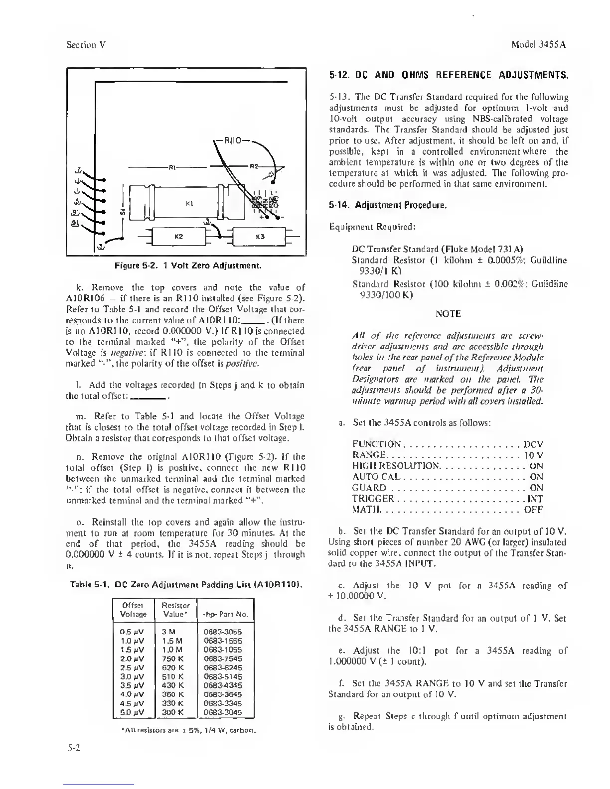
k.
Remove the
top
covers and note the value
of
A10R106
—
if there is an R1 10 installed (sec Figure 5-2).
Refer to Table
5-1
and record the Offset
Voltage
that cor-
responds to the current
value
of AlORl 10: (If there
is
no AlORl
10,
record 0.000000 V.) If R1
10
is
connected
to the terminal marked
“+”.
the polarity of the Offset
Voltage
is
negative:
if
RllO is connected
to
the terminal
marked the polarity of the offset is positive.
l. Add the voltages recorded in Steps
j
and
k
to
obtain
the total offset:
m.
Refer
to Table
5-1
and locate
the Offset Voltage
that is closest
to
the
total offset
voltage recorded in Step I.
Obtain a resistor that corresponds to that offset voltage.
n.
Remove
the original
AlORl
10
(Figure 5-2). If the
total offset (Step I) is positive, connect the new RllO
between the unmarked terminal and the terminal marked
if the total offset is
negative,
connect it between the
unmarked terminal and the terminal marked
“+”.
o. Reinstall the top covers and again allow the instru-
ment to
run
at room
temperature
for
30 minutes.
At
the
end of that period, the 34SSA reading should be
0.000000 V
± 4
counts. If it is not. repeat Steps
j
through
n.
Table
5-1.
DC
Zero Adjustment Padding
List (A10R110).
Offset
Voltage
Resistor
Value*
-hp-
Part
No.
0.6 mV
3M 0683-3055
1.0 mV
1.5 M 0683-1555
1.6
mV
1.0 M
0683-1055
2.0
mV
750 K
0683-7545
2.5 mV 620
K 0683-6245
3.0
mV
510 K
0683-5145
3.5 mV
430
K
0683-4345
4.0
mV
360 K 0683-3645
4.6
mV
330K 0683-3345
5.0
mV
300 K
0683-3045
*AII resistors are
t
5%,
1/4 W.
Carbon.
5-12.
DC AND OHMS REFERENCE ADJUSTMENTS.
S-i3. The IX Transfer Standard required for the following
adjustments
must be adjusted for optimum I-volt and
10-volt output accuracy
using
NBS-calibrated voltage
standards. The Transfer Standard should
be
adjusted just
prior to use. After adjustment, it should be left on and, if
possible,
kept in a controlled
environment where
the
ambient temperature is within one or two degrees
of the
temperature
at
which
it was adjusted. The following pro-
cedure should
be
performed
in that same
environment.
S-14.
Adjustment Procedure.
Equipment Required:
DC Transfer Standard (Ruke Model
731 A)
Standard Resistor
(1
kilohm
±
0.0005%;
Guildline
9330/1 K)
Standard Resistor (100 kilohm
1
0.002%:
Guildlinc
9330/100 K)
NOTE
Ail
of
the reference adjustments are screw-
driver adjustments
and are accessible through
holes in the rear panel
of
the
Reference Module
(rear panel
of
instrument). Adjustment
Designators
are marked on the panel The
adjustments
should be performed
after
a
30-
minute warmup
period with all covers installed.
a. Set the 3455A controls as follows:
FUNCTION
DCV
RANGE
10
V
HIGH RESOLUTION
ON
AUTO
CAL ON
GUARD
ON
TRIGGER
INT
MATH OFF
b.
Set
the DC Transfer Standard
for an
output
of 10
V.
Using short pieces of
number 20
AWG
(or larger) insulated
solid
copper wire, connect the output
of the Transfer Stan-
dard to the 3455A INPUT.
c.
Adjust the 10 V
pot for a 3455A reading of
t
10.00000 V.
d.
Set the Transfer
Standard for an output of 1 V. Set
the
34S5A RANGE to I V.
e.
Adjust
the 10:1 pot for a 345SA reading of
1.000000 V(± 1 count).
f. Set the
3455A
RANGF.
to 10
V
and set the Transfer
Standard for an output
of
10 V.
g.
Repeat
Steps c through f until optimum adjustment
is obtained.
5-2
 Loading...


