Section Vllt Model 3455A
THEORY
OF
OPERATION
8-10.
INTRODUCTION.
8-11.
The following paragraphs contain both agcneraland
detailed description of the methods and circuits used in the
Model
34S5A
Multimeter. The
general
description explains
the basic purpose of each block
of
the functional block
diagram shown in Figure
8-1.
The detailed description
describes
the methods and pertinent circuitry
used
to
accomplish
the function of each block of the detailed block
diagram.
8-12.
INPUT SWITCHING AND DC ATTENUATOR.
8-13.
General.
8-14.
The front or rear input terminals of the 34SSA arc
selected by a two-section rotary switch located on the
rear panel of the instrument. Reed relays are used to per-
form all internal input switching where
voltages
greater
than
17
volts
may be encountered. All other input switch-
ing is done with FF.T switches.
8-15. Detailed
Description.
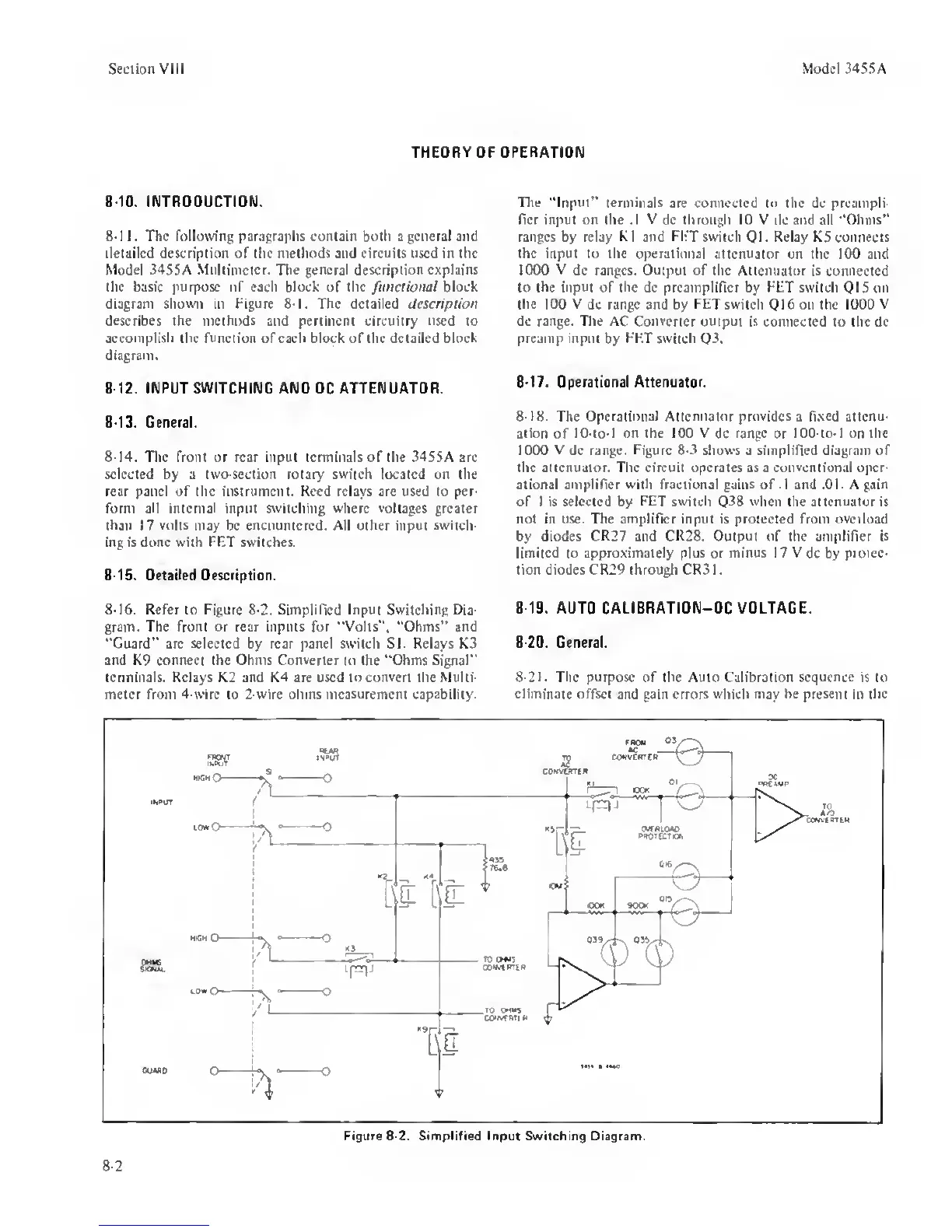
8-16.
Refer to Figure 8-2. Simplified
Input
Switching E)ia-
gram. The front or rear inputs for ‘'Volts”, “Ohms” and
"Guard” are selected by rear panel switch SI. Relays K3
and
K9 connect the Ohms Converter to
the
"Ohms Signal”
terminals. Relays K2 and K4 are used to convert the Multi-
meter from 4-wirc to 2-wire ohms measurement capability.
The "Input" terminals
are connected to the dc preampli-
fier input on the .1 V dc thruugli 10 V
dc and all
‘Ohms”
ranges by relay K1 and FFT switch Ql. Relay KS connects
the input to the operational attenuator
on the 100 and
1000 V dc ranges. Output of the Attenuator
is connected
to the input of the dc preamplifier by FET switch
01 S on
the 100 V
dc range and by
FET
switch Q16 on the 1000 V
dc
range. The
AC
Converter output is
connected to the dc
preamp input
by
FET switch
Q3.
8-17.
Operational Attenuator.
8-18.
The
Operational
Attenuator
provides
a fixed attenu-
ation of 10-to-l
on the 100 V
dc
range
or
IOO-to-1 on
the
1000 V dc range. Figure
8-3
shows a simplified diagram of
the attenuator. The circuit operates as a conventional oper-
ational amplifier with fractional gains of
.1
and
.01.
A gain
of I is selected by
FET
switch Q38 when the attenuator is
not in use. The amplifier input is protected from
overload
by diodes
CR27
and CR28. Output of the amplifier is
limited to
approximately plus
or
minus 17 V
dc by protec-
tion diodes CR29 throu^ CR31.
8-19.
AUTO CALiBRATION-DC VOLTAGE.
8-20.
General.
8-21.
The
purpose
of the Auto Calibration sequence is to
eliminate offset
and gain
errors
which may
he present
in the
8-2
Figure
8-2.
Simplified input Switching Diagram.
 Loading...


