Model 3455A
THEORY OF
OPERATION Section VIII
Figure 8-3. Operational Attenuator
Diagram.
analog circuitry of the
Voltmeter. This is accomplished by
measuring the
offset and gain errors and
mathematically
correcting for
them.
Each
error
measurement is stored in
“memory”
by
the main controller
as a constant. These
constants are sequentially
updated. The output reading of
the
Voltmeter
is computed by
the Main Controller and is
equal to the ratio of the external
input to the internal refer-
ence, times a
range factor. Figure
8-4
shows a very basic
diagram
of the Voltmeter.
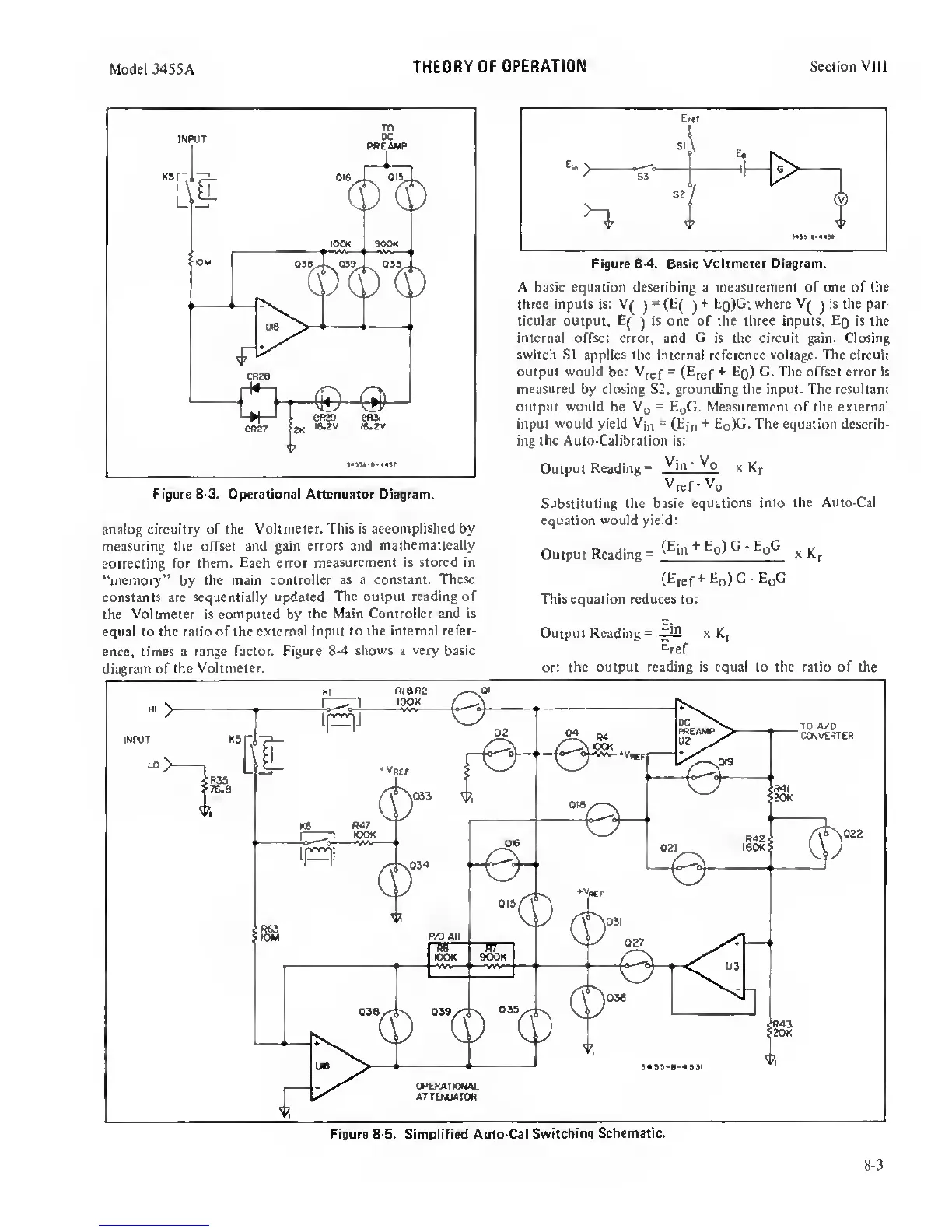
A basic equation describing a measurement of one of the
three inputs is: V(
)
= (E(
)
+
Eq)G
;
where V(
^
is the par-
ticular output,
E(
)
is one of the three inputs.
Eq
is the
internal offset error, and
G
is the circuit gain. Closing
switch SI applies
the internal reference
voltage. The circuit
output would be:
Vjef
=
(Eref
*
^O)
offset error is
measured
by
closing S2, grounding the input. The resultant
output would
be
Vg
=
EqG. Measurement of the external
input would yield
Vjn
=
(Ejn
+
EoX*-
The equation
describ-
ing the Auto-Calibration is:
Output
Reading®
_fh
'
x
Kr
Yref'
Yq
Substituting the basic
equations into the Auto-Cal
equation would yield:
Output Reading
=
Eq)
G
•
EpC
(Etef
*
Eg) G
-
EgG
This equation reduces
to:
Output Reading
®
x
Eref
or:
the output reading is equal to the ratio of the
8-3
 Loading...


