Model 3455A
THEORY OF OPERATION Section VIII
Offset Error Measurement. The
DC Preamp
input is
grounded through a 100
kjlohm resistor by
FET switch
AI0Q2. A DC Preamp gain of XI is selected
by
FET switch
A10Q19. The resultant measurement is the offset
voltage
present
on (he 10
V
dc range. This number is stored by the
main controller for use in correcting measurements made
on the 10
V
dc range.
8*25. 1
V
dc and .1
V dc
Input Offset Error
Measurensent.
Offset error measurements on the 1
V
dc and
. 1 V
dc
ranges
arc made in the same manner
as the 10 V dc range except
for IX
Preamp
gains of XIO for the I
V
dc range
and XI 00
for
the .1 V
dc
range.
The
circuit configuration for the I
V
dc
Offset Error Measurement is shown in
Figure 8-7.
A DC
Preamp gain
of
XIO is selected
by
FET switch
A10Q2I.
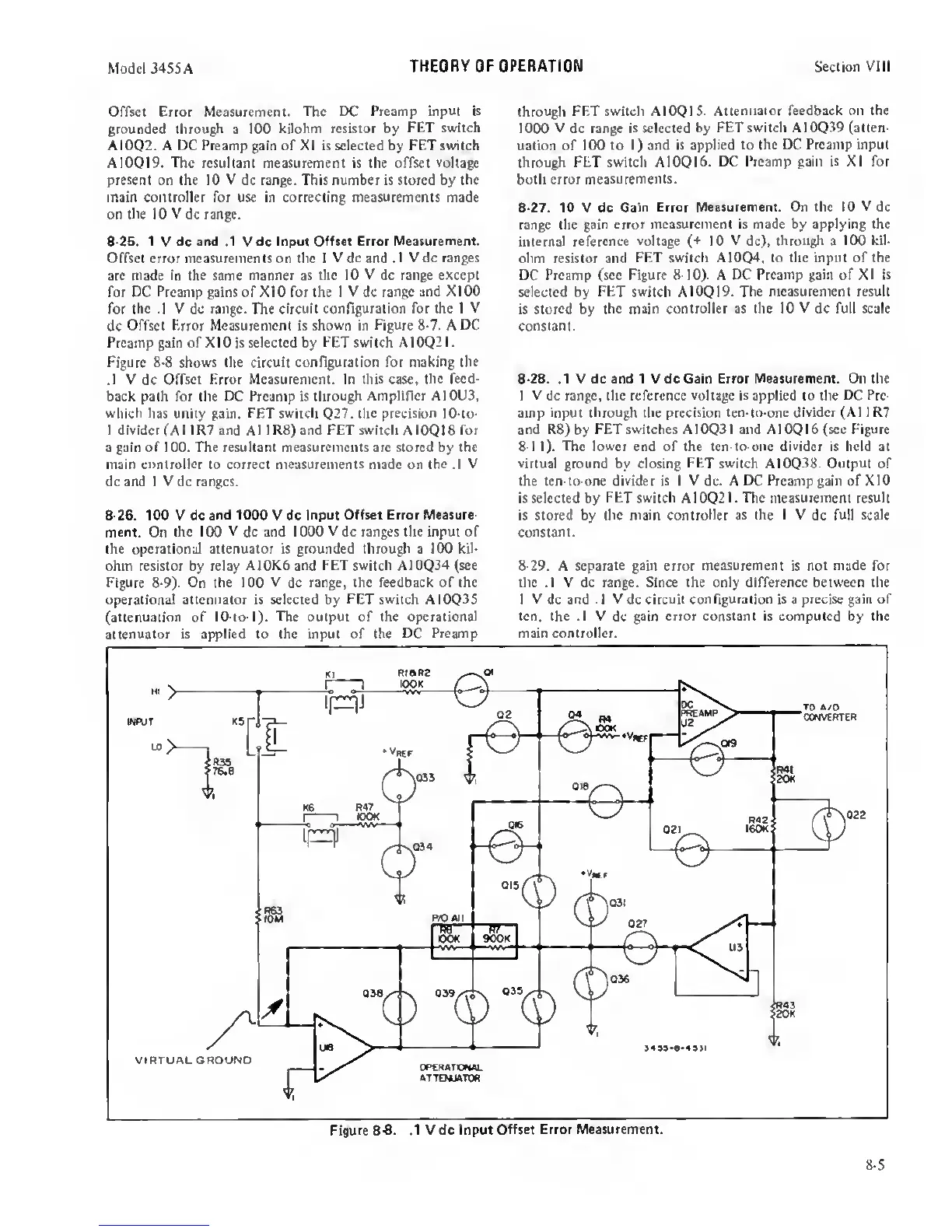
Figure 8-8 shows
the
circuit configuration for making
the
.1 V
dc
Offset Error Measurement. In this case,
the feed-
back path for the DC fVeamp is
through Amplifier A10U3,
which has unity gain.
FET switch
Q27. the
precision
10-to-
1
divider
(A
1
1
R7 and
A 1 1
R8)
and FET switch
A I
OQ
1 8
for
a gain of 100. The resultant measurements arc stored
by
the
main controller to correct
measurements
made on (he .1
V
dc and I
V
dc ranges.
8-26.
100 V dc and
1000
V dc
Input Offset Error Measure-
ment.
On
the 100 V dc and 1000 V dc ranges the input of
the operational attenuator is grounded through a 100
kil-
ohm resistor by relay
A10K6 and FET switch
A10Q34
(see
Figure 8-9).
On
the
100
V
dc
range, the feedback of the
operational attenuator is selected by FET switch A10Q3S
(attenuation
of
10-to-l). The output of the operational
attenuator is applied to the input of the DC
Preamp
throu^
FET switch AIOQIS.
Attenuator feedback on the
1000 V
dc
range is selected by
FET switch A10Q39 (atten-
uation of 100 to
1)
and is applied to
the DC Preamp input
through FET switch A10QI6.
DC Preamp gain is XI for
both error
measurements.
8-27.
10 V dc Gain
Error Measurement. On the 10 V dc
range the gain error
measurement is made by applying the
internal
reference
voltage
(-*-
10
V
dc),
throu^
a
100
kil-
ohm resistor and
FET switch
A1004,
to the input of the
DC Preamp (see Figure
8-10).
A EX Preamp gain of XI
is
selected by
FET
switch A10Q19.
The measurement result
is stored by
the main controller as the 10
V
dc full scale
constant.
8-28.
.1 V dc and 1 V dc Gain Error Measurement. On the
1 V dc range, the reference
voltage
is applied to the DC
Pre-
amp input through the precision ten-to-one
divider (AI 1 R7
and
R8)by FET switches A10Q31 and A10QI6(sec Figure
8-11). The lower end of the ten-to-one
divider
is held at
virtual
ground by closing
FET
switch AI0Q38. Output of
the ten-to-one
divider
is I
V
dc. A DC Preamp gain of
XIO
is selected by
FET switch
A10Q21. The
measurement result
is stored by (he main
controller as
the
I V
dc full
scale
constant.
8-29.
A
separate
gain error
measurement
is not
made
for
the .1 V dc range. Since the only difference between the
1
V
dc and
.1 V
dc
circuit configuration is
a
precise gain
of
ten,
the
.1 V
dc
gain error constant is computed by the
main controller.
8-5
 Loading...


