ENWW Engine control system 109
2 See “Secondary transfer roller engaging/disengaging control” on page 5-166.
3 The sequences inside the dotted-line box are performed when required.
4 The color misregistration control controls the correction of both horizontal and vertical
misregistration. See Color misregistration control, later in this chapter, for more information.
5 The image stabilization control controls the correction of the high-voltage bias output value
and VIDEO signal PWM value for a stable image. See Image stabilization control, later in this
chapter, for more information.
6 The automatic paper delivery system is activated if a residual paper is detected.
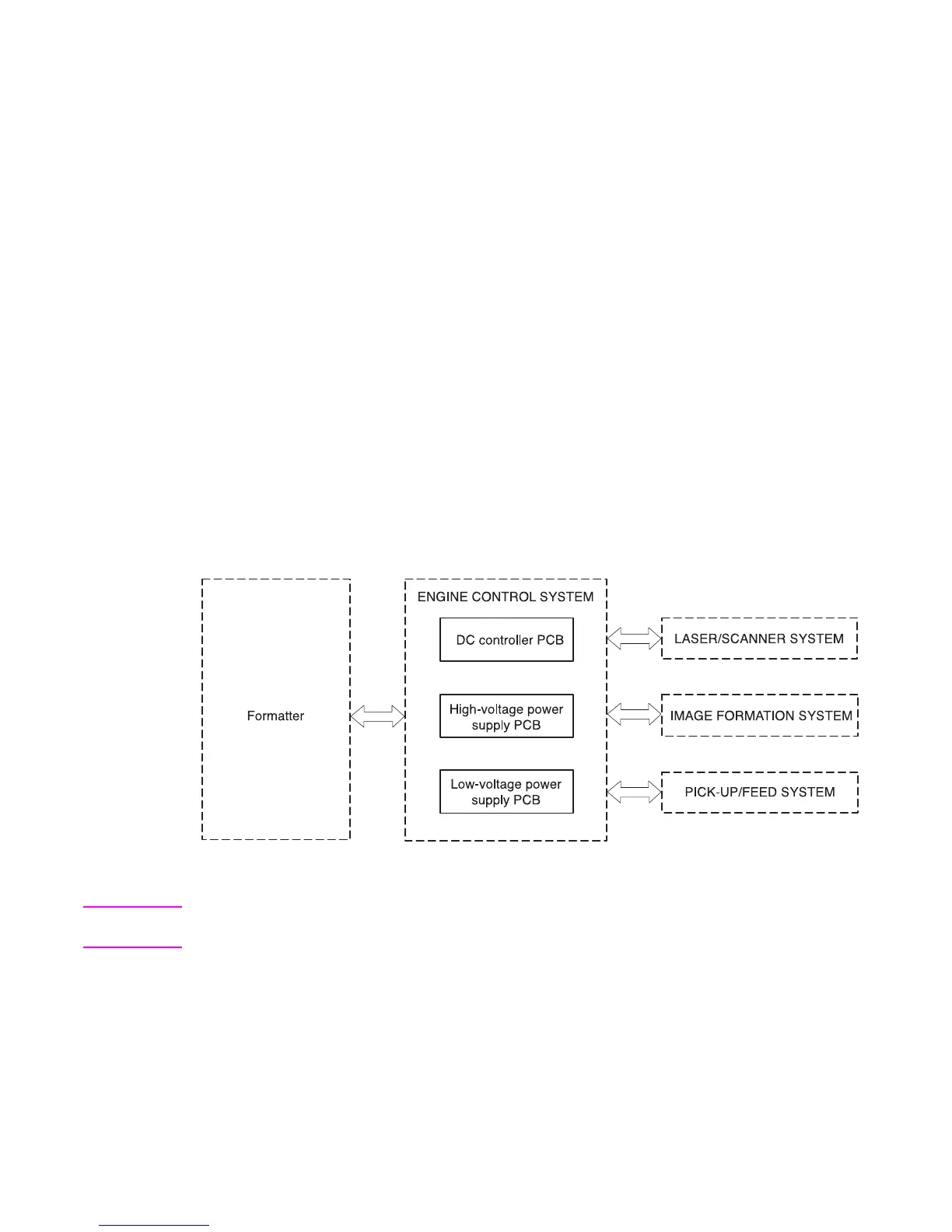
Engine control system
The engine control system functions as the brain of the printer. It controls the laser/scanner
system, the image formation system, and the pickup/feed system according to the commands
received from the formatter.
The engine control system consists of the following:
● DC controller printed circuit board (PCB) assembly
● high-voltage power supply PCB
● low-voltage power supply PCB
The block diagram below illustrates the engine control system. Each circuit is described in the
following paragraphs.
Figure 5-3 Engine control system
Note Components described as a PCB may consist of a single circuit board or a circuit board plus other
parts, such as cables and sensors.

 Loading...