2-12. To obtain permanent records of 412Areadings, connect a recorder to the
OC
AMPLIFIER OUTPUT
connector and operate the '412A as directed above. The output of the 412A is 1 volt at full scale;
ti
necessary,
Externally attenuate the 412A output to match it with recorder sensitivity. Maximum rated load current from
the 412A is 1 ma. A load resistance of less than 1000 ohms may cause the load current to exceed
1 ma and thus cause errors in meter indication and amplifier gain.
SECTION 111
CIRCUIT OPERATION
3-1.
GENERAL
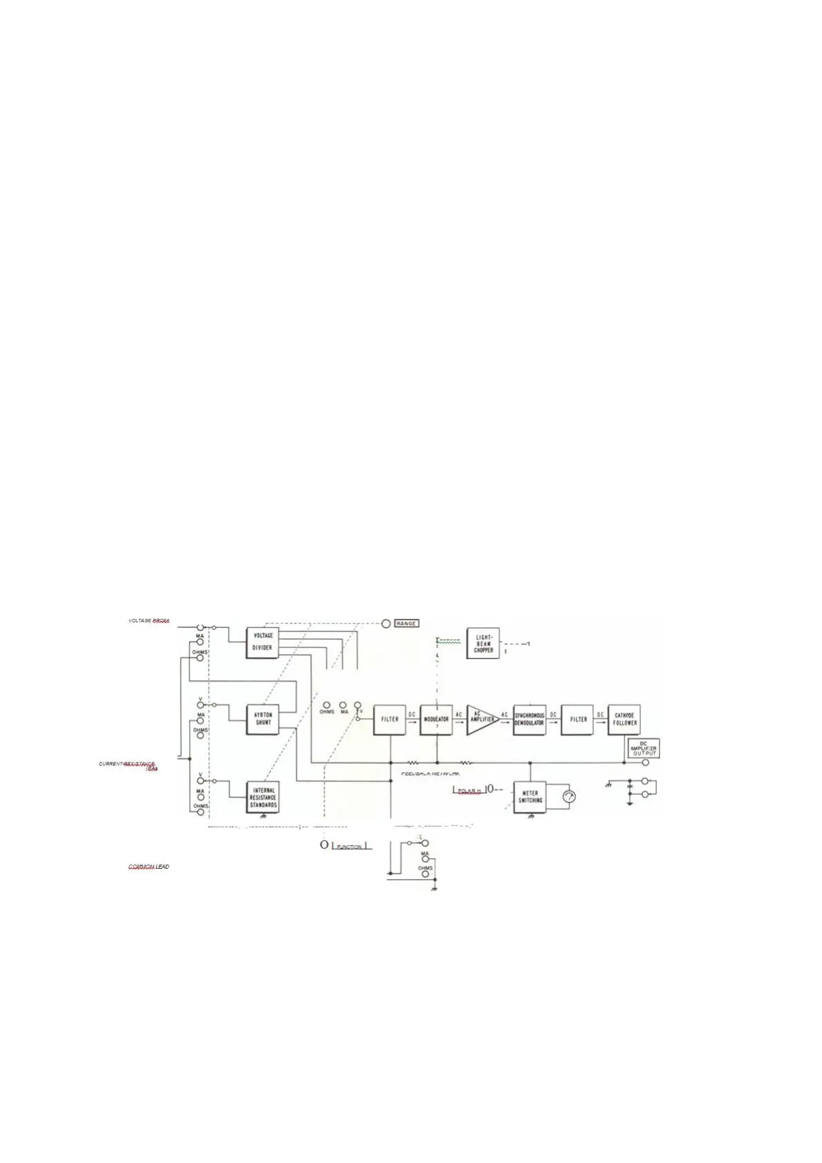
3-2. The Model 412A is basically a
O
to 0.9 millivolt dc voltmeter. Precision voltage dividers, shunts,
and reference resistors extend the range of the baste voltmeter and permit current and resistance
measurements as well.
3-3.
CIRCUIT OPERATION.
3-4. With the FUNCTION selector and RANGE switch properly set, voltage is applied to a photoconductive
modulator through a low-pass filter. See figure 3-1.
The filter attenuates ac components present on any input signal, and the modulator converts the remaining
dc component to a square wave. A synchronous-motor-driven, light-beam chopper sets modulator frequency
at 5/6 power-line frequency. An ac-coupled amplifier amplifies modulator output about 500,000 times.
A demodulator synchronized with the modulator by the light-beam chopper, converts amplifier output to
de,
The output of the demodulator is filtered and applied through a cathode follower to 1) a feedback network,
2) the DC AMPLIFIER OUTPUT terminals and 3) an output indicator. The feedback network stabilizes
the dc gain of the modulator-amplifierdemodulator system to a value of 1111, thereby providing an output
of 1 volt for an input of 0.9 millivolt.
The output indicator is a 0-1 voltmeter. The POLARITY switch permits reversal of indicator connections,
if required, to obtain up-scale readings.
The POLARITY switch is disabled when the FUNCTION selector is set to OHMS.
SERVICING ETCHED CIRCUIT BOARDS
Excessive heat or pressure can lift the copper strip from the board. Avoid damage by using a low power
soldering iron (SO watts maximum) and following these instructions. Copper that lifts off the board should
be cemented in place with a quick drying acetate base cement having good electrical insulating properties.
A break in the copper should be repaired by soldering a short length of tinned copper wire across the break.
Use only high qua lit y rosin core solder when repairing etched circuit boards. NEVER USE PASTE FLUX.
After soldering, clean off any excess flux and coat the repaired area with a high quality electrical varnish
or lacquer.
 Loading...


