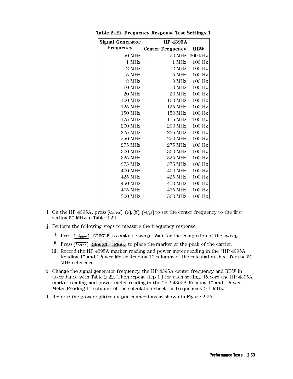
Table 2-22. Frequency Response Test Settings 1
Signal Generator
Frequency
HP 4395A
Center Frequency RBW
50 MHz 50 MHz 300 kHz
1 MHz 1 MHz 100 Hz
2 MHz 2 MHz 100 Hz
5 MHz 5 MHz 100 Hz
8 MHz 8 MHz 100 Hz
10 MHz 10 MHz 100 Hz
20 MHz 20 MHz 100 Hz
100 MHz 100 MHz 100 Hz
125 MHz 125 MHz 100 Hz
150 MHz 150 MHz 100 Hz
175 MHz 175 MHz 100 Hz
200 MHz 200 MHz 100 Hz
225 MHz 225 MHz 100 Hz
250 MHz 250 MHz 100 Hz
275 MHz 275 MHz 100 Hz
300 MHz 300 MHz 100 Hz
325 MHz 325 MHz 100 Hz
375 MHz 375 MHz 100 Hz
400 MHz 400 MHz 100 Hz
425 MHz 425 MHz 100 Hz
450 MHz 450 MHz 100 Hz
475 MHz 475 MHz 100 Hz
500 MHz 500 MHz 100 Hz
i. On the HP 4395A, press
4
Center
5
,
4
5
5
,
4
0
5
,
4
M/
5
to set the center frequency to the rst
setting 50 MHz in Table 2-22.
j. Perform the following steps to measure the frequency response.
i.
Press
4
Trigger
5
,
NNNNNNNNNNNNNNNNNNNN
SINGLE
to make a sweep.Wait for the completion of the sweep.
ii.
Press
4
Search
5
,
N
NNNNNNNNNNNNNNNNNNNNNNNNNNNNNNNNNNNNN
SEARCH: PEAK
to place the marker at the peak of the carrier.
iii. Record the HP 4395A marker reading and power meter reading in the \HP 4395A
Reading 1" and \Power Meter Reading 1" columns of the calculation sheet for the 50
MHz reference.
k. Change the signal generator frequency, the HP 4395A center frequency and RBW in
accordance with Table 2-22. Then repeat step 1-j for each setting. Record the HP 4395A
marker reading and power meter reading in the \HP 4395A Reading 1" and \Power
Meter Reading 1" columns of the calculation sheet for frequencies
1 MHz.
l. Reverse the power splitter output connections as shown in Figure 2-25.
Performance Tests 2-63
 Loading...


