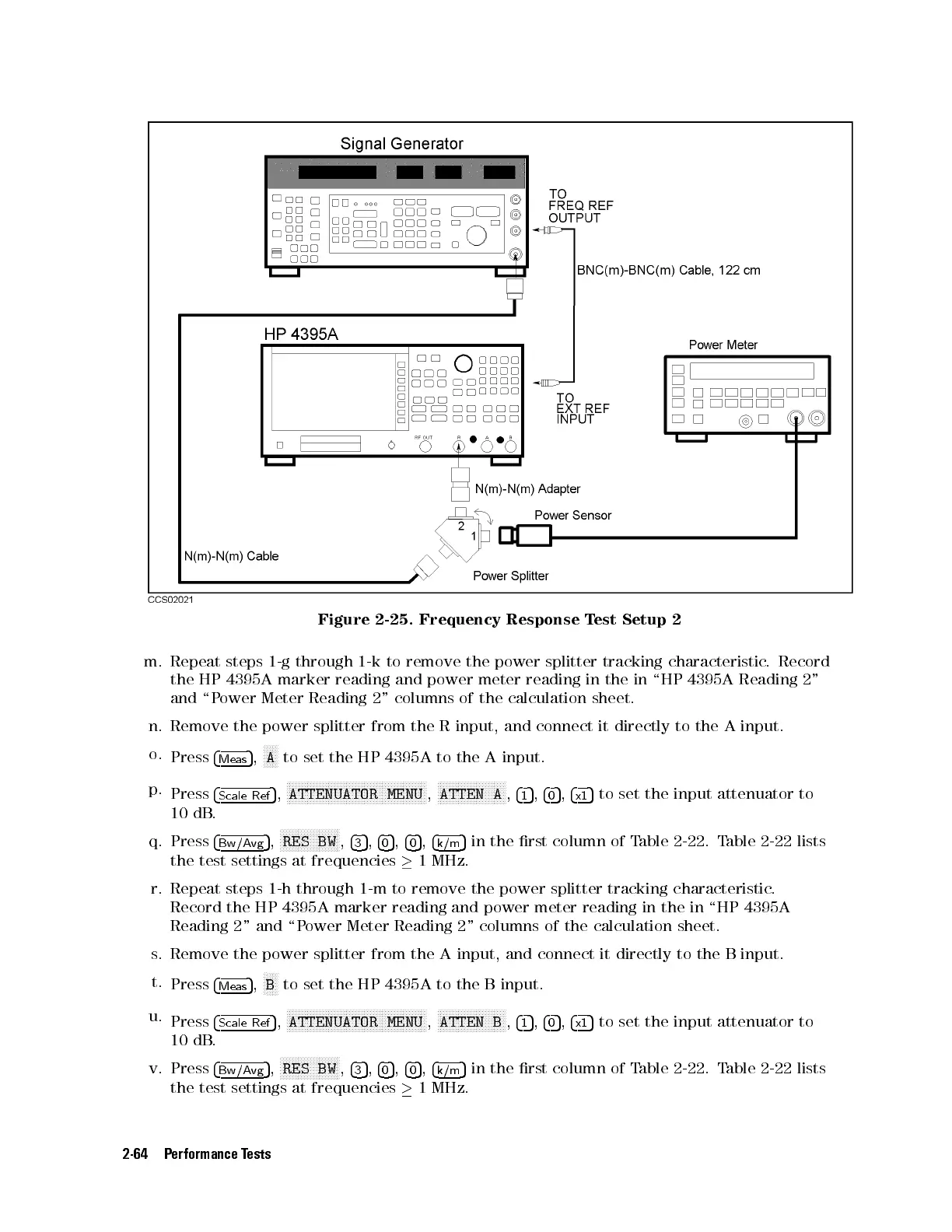
Figure 2-25. Frequency Response Test Setup 2
m. Repeat steps 1-g through 1-k to remove the power splitter tracking characteristic
. Record
the HP 4395A marker reading and power meter reading in the in \HP 4395A Reading 2"
and \Power Meter Reading 2" columns of the calculation sheet.
n. Remove the power splitter from the R input, and connect it directly to the A input.
o.
Press
4
Meas
5
,
N
NNNN
A
to set the HP 4395A to the A input.
p.
Press
4
Scale Ref
5
,
NNNNNNNNNNNNNNNNNNNNNNNNNNNNNNNNNNNNNNNNNNNNNNN
ATTENUATOR MENU
,
NNNNNNNNNNNNNNNNNNNNNNN
ATTEN A
,
4
1
5
,
4
0
5
,
4
x1
5
to set the input attenuator to
10 dB.
q. Press
4
Bw/Avg
5
,
NNNNNNNNNNNNNNNNNNNN
RES BW
,
4
3
5
,
4
0
5
,
4
0
5
,
4
k/m
5
in the rst column of Table 2-22. Table 2-22 lists
the test settings at frequencies
1 MHz.
r. Repeat steps 1-h through 1-m to remove the power splitter tracking characteristic
.
Record the HP 4395A marker reading and power meter reading in the in \HP 4395A
Reading 2" and \Power Meter Reading 2" columns of the calculation sheet.
s. Remove the power splitter from the A input, and connect it directly to the B input.
t.
Press
4
Meas
5
,
N
NNNN
B
to set the HP 4395A to the B input.
u.
Press
4
Scale Ref
5
,
NNNNNNNNNNNNNNNNNNNNNNNNNNNNNNNNNNNNNNNNNNNNNNN
ATTENUATOR MENU
,
NNNNNNNNNNNNNNNNNNNNNNN
ATTEN B
,
4
1
5
,
4
0
5
,
4
x1
5
to set the input attenuator to
10 dB.
v. Press
4
Bw/Avg
5
,
NNNNNNNNNNNNNNNNNNNN
RES BW
,
4
3
5
,
4
0
5
,
4
0
5
,
4
k/m
5
in the rst column of Table 2-22. Table 2-22 lists
the test settings at frequencies
1 MHz.
2-64 Performance Tests
 Loading...


