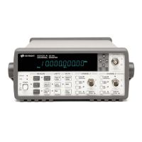
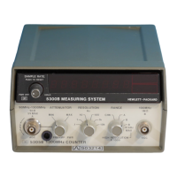
Model 5305B
Circuit Dia
rams
SECTION IX E
5305B 1100 MHz COUNTER
SUBSECTION VIII
CIRCUIT DIAGRAMS
9E-8-1. INTRODUCTION
c. Component location views of the printed-circuit
boards.
d. Schematic diagrams of the counter
.
9E-8-2. This subsection of the manual contains the
followin
information:
a. A signal list that gives the signal name and con-
nector pin number of each signal that intercon-
nects with the mainframe (see Table 9E-8-1).
b. Signal waveforms at key points in the input
amplifiers and clock circuits.
9E-8-3. Use the information in this subsection in con-
junction with the information provided in Subsection V,
Maintenance, while troubleshootin
the counter.
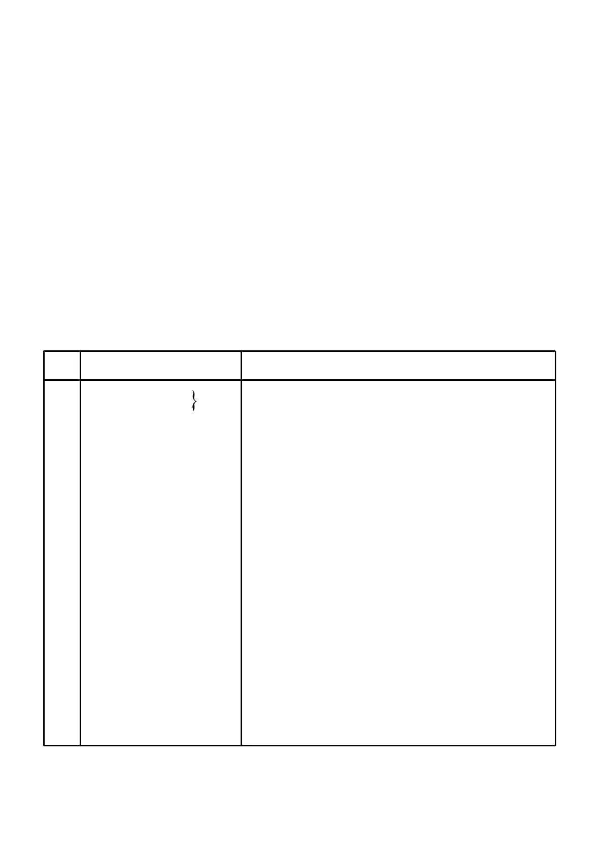
Table 9E-8-1. Counter Signal List
9E-8-1
PIN
NO.
SIGNAL NAME DESCRIPTION
1 +5V Circuit operating voltages.
2 -5V
3 -17V
4 COMMON RETURN Common power and signal return line.
Signal to be countend in the mainframe.
5 F1 Goes low when the mainframe counter reaches 9% full-scale.
6 "9" Tied to pin 14.
7 F2 Time Base Clock 10 MHz or 10 MHz ÷16.
8 INHIBIT High during the measurement cycle, low during the display cycle.
Low signal forces the main gate flip-flop in the mainframe
9 OPEN to the open position.
Low signal forces the main gate flip-flop in the mainframe
10 CLOSE to the closed position.
11 LOG Logarithmic pulse tram from time base triggers main gate flip-
12 NC flop on rising edge.
Inverted log pulses while main gate in mainframe is open
13 EXPONENT indicates number of auto-ranging steps.
Low signal enables overflow and storage.
14 OVERFLOW
High signal resets all registers.
15 RESET
10 MHz reference signal from mainframe crystal oscillator.
16 CLOCK
Low signal enables closing of the main gate in the mainframe
17 MAX TIME on next log pulse. Rising edge initiates display cycle.
Output from the time base decade that is selected by the
18 TIME BASE OUTPUT time base select code on pins 22, 23, and 24.


 To Next Page