3
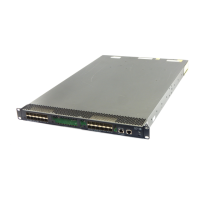
Figure 3 HP 5920AF-24XG/HP 5920AF-24XG TAA left side panel
(1) Primary
point 1
HP 5900AF-48XG-4QSFP+/HP
5900AF-48XG-4QSFP+ TAA panel views
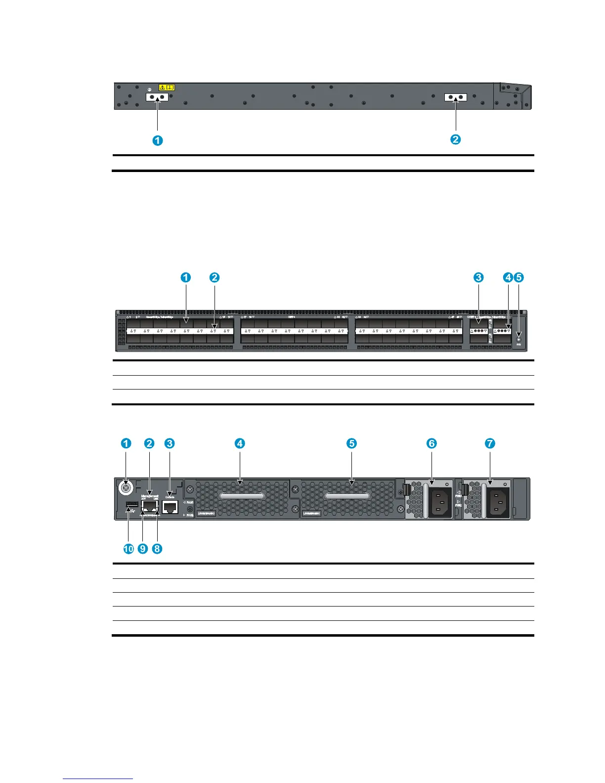
Figure 4 HP 5900AF-48XG-4QSFP+/HP 5900AF-48XG-4QSFP+ TAA front panel
(1) SFP+ port (2)
(3) QSFP+ port (4) QSFP+ port LED
(5) System status LED (SYS)
Figure 5 HP 5900AF-48XG-4QSFP+/HP 5900AF-48XG-4QSFP+ TAA rear panel
(1) Grounding screw (auxiliary grounding point 2) (2) Management Ethernet port
(3) Console port (4) Fan tray slot 1
(7) Power supply slot 2 (8) LINK LED for the management Ethernet port
(9)
The HP 5900AF-48XG-4QSFP+ and 5900AF-48XG-4QSFP+ TAA switches come with the power supply
slots empty and the filler modules for the slots as accessories. You can install one or two power supplies
for the switch as needed. In this figure, two 650W AC power supplies are installed. For more information
about installing and removing the power supply, see "Installing/removing a power supply."
 Loading...


