EasyManuals Logo

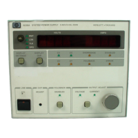
HP 6038A Service Manual

HP 6038A
44 pages
To Next Page IconTo Next Page
To Previous Page IconTo Previous Page
Page #3 background imageLoading...
Page #3 background image
CONTENTS
1-1
INTRODUCTION.1-1
1-3
DESCRIPTION.1-1
1-12
SAFETY
CONSIDERATIONS.M
1-14
SPECIFICATIONS.1-1
1-16
OPTIONS.1-1
1-18
ACCESSORIES.1-2
1-20
INSTRUMENT
AND
MANUAL
IDENTIFICATION...1-2
1-23
HP-IB
INTERCONNECTION
CABLES
AND
CONNECTORS.1-3
1-26
ORDERING
ADDITIONAL
MANUALS.1-3
1-28
RELATED
DOCUMENTS.1-3
1-30
HP-IB
COMPATIBILITY.1-3
3-71
Constant
Current
Operation.3-11
3-73
Return
to
Local.3-11
3-76
HP-IB
OPERATION.3-11
3-77
Interface
Functions.3-11
3-91
HP-IB
Address
Selection.3-13
3-97
Power-On
Service
Request.3-13
3-100
Initial
Conditions.3-14
3-102
Programming
Syntax.3-14
3-194
ANALOG
PROGRAMMING.3-25
3-207
MULTIPLE-SUPPLY
OPERATION.3-27
3-209
Auto-Parailei
Operation.3-27
3-219
Series
Operation.3-28
3-221
Fault
Indicator
(FLT)
and
Remote
Inhibit
{lNH)...3-29
2-1
INTRODUCTION.2-1
2-3
INITIAL
INSPECTION.2-1
2-5
Mechanical
Check.2-1
2-7
Electrical
Check.2-1
2-9
PREPARATION
FOR
USE.2-2
2-11
Location
and
Cooling.2-2
2-13
Outline
Diagram.2-2
2-15
Bench
Operation.2-2
2-17
Rack
Mounting.2-2
2-19
Input
Power
Requirements.2-2
2-21
Power
Connection.2-2
2-25
LINE
VOLTAGE
OPTION
CONVERSION.2-2
2-27
REPACKAGING
FOR
SHIPMENT.2-3
3-1
INTRODUCTION.3-1
3-3
CONTROLS
AND
INDICATORS.3-1
3-5
OUTPUT
RANGE
FOR
AN
AUTORANGING
POWER
SUPPLY.3-1
3-12
TURN-ON
CHECKOUT
PROCEDURE.3-4
3-18
INITIAL
SETUP
AND
INTERCONNECTIONS.3-5
3-19
Connecting
the
Load.3-5
3-31
Overvoltage
Protection
(OVP).3-7
3-35
Foldback
Protection.3-8
3-40
Remote
Voltage
Sensing.3-8
3-46
Mode
Switches.3-9
3-49
HP-IB.3-9
3-54
Monitor
Signals.3-10
3-56
Protective
Circuits.3-10
3-65
LOCAL
OPERATION.3-10
3-69
Constant
Voltage
Operation.3-11
4-1
INTRODUCTION.4-1
4-7
HP-IB
BOARD.4-1
4-9
HP-IB
Transceivers
and
Interface
Circuits.4-1
4-11
Microprocessor
and
Clock
Circuits.4-1
4-15
Data
Bus
Latches
and
Free-Run
Jumper.4-1
4-18
Address
Decoding.4-2
4-21
Memory
Circuits.4-2
4-24
Start-Up
Circuits.4-4
4-26
Address
Switches.4-4
4-29
Test
LEDs.4-4
4-31
Real-Time
Clock.4-4
4-33
Serializer.4-4
4-43
Fault
Indicator
(FLT)
Circuit.4-5
4-46
Remote
inhibit
(INH)
Circuit.4-5
4-48
POWER
SUPPLY
INTERFACE
(PSD
BOARD.4-5
4-52
Isolation.4-5
4-54
Control
Lines
Output
Port.4-5
4-56
Address
Latches
and
Decoders.4-5
4-59
Output
Latches.4-5
4-62
Current
and
Voltage
DACs.4-7
4-65
Analog
Multiplexer.4-7
4-67
Successive
Approximation
A-to-D
Converter.4-7
4-69
A-To-D
Input
Port.4-7
4-72
Status
Lines
input
Port.4-7
4-74
Identification
Input
Port.4-7
4-78
Power
Clear.4-7
4-80
FRONT
PANEL
BOARD.4-7
4-82
Address
Latches
and
Decoders.4-8
4-84
Volts
and
Amps
Output
Ports
and
Displays.4-8
4-87
RPG
and
Latches.4-8
4-90
Front-Panel
Controls
Input
Port.4-8
4-92
Mode
Indicators.4-8
4-94
OVP
ADJUST
CONTROL.4-8
4-96
Power
Clear.4-8
4-98
POWER
MESH
AND
CONTROL
BOARD.4-8
4-100
AUTORANGING
POWER.4-8
4-102
BLOCK
DIAGRAM
OVERVIEW.4-9
4-110
SIMPLIFIED
SCHEMATIC.4-10

Questions and Answers:

Question and Answer IconNeed help?

Do you have a question about the HP 6038A and is the answer not in the manual?

HP 6038A Specifications

General IconGeneral
BrandHP
Model6038A
CategoryInverter
LanguageEnglish

Related product manuals