EasyManuals Logo

HP 8340b User Manual

HP 8340b
530 pages
To Next Page IconTo Next Page
To Previous Page IconTo Previous Page
Page #374 background imageLoading...
Page #374 background image
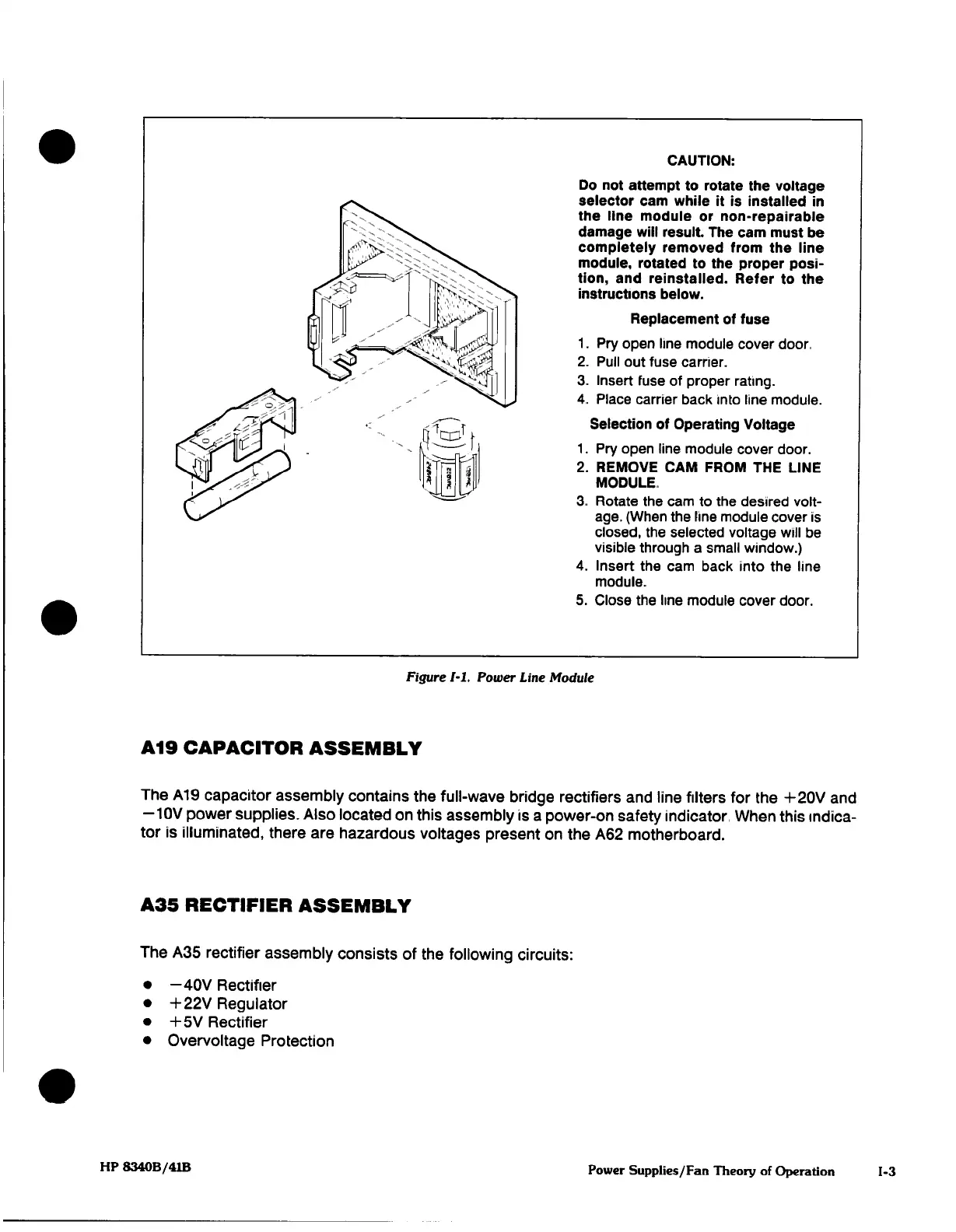
CAUTION:
Do
not
attempt
to
rotate
the
voltage
selector cam
while
it
is
installed
in
the
line
module
or
non-repairable
damage
will
result.
The
cam
must
be
completely
removed from
the
line
module,
rotated to the
proper
posi¬
tion,
and
reinstalled. Refer
to the
instructions
below.
Replacement
of
fuse
1.
Pry
open
line
module
cover door,
2.
Pull
out
fuse
carrier.
3.
Insert
fuse of
proper
rating.
4.
Place
carrier
back
into
line
module.
Selection
of
Operating
Voltage
1.
Pry
open
line
module
cover
door.
2.
REMOVE
CAM FROM THE
LINE
MODULE
3.
Rotate
the
cam
to
the desired
volt¬
age.
(When
the
line
module
cover
is
closed,
the
selected
voltage
will
be
visible
through
a
small
window.)
4.
Insert
the
cam
back
into
the
line
module.
5.
Close
the
line
module
cover door.
Figure 1-1.
Power
Line
Module
A19 CAPACITOR
ASSEMBLY
The
A19
capacitor
assembly contains
the
full-wave
bridge
rectifiers
and
line
filters for
the
+20V
and
—10V
power
supplies.
Also
located
on
this
assembly
is
a
power-on
safety
indicator When
this
indica¬
tor
is
illuminated,
there
are hazardous
voltages
present
on
the
A62
motherboard.
ASS
RECTIFIER
ASSEMBLY
The
ASS
rectifier
assembly consists
of the
following
circuits:
•
-40V
Rectifier
•
+22V
Regulator
•
+5V
Rectifier
•
Overvoltage
Protection
HP 8340B/41B
Power Supplies/Fan Theory
of
Operation

Table of Contents

Other manuals for HP 8340b

Questions and Answers:

Question and Answer IconNeed help?

Do you have a question about the HP 8340b and is the answer not in the manual?

HP 8340b Specifications

General IconGeneral
BrandHP
Model8340b
CategoryInverter
LanguageEnglish

Related product manuals